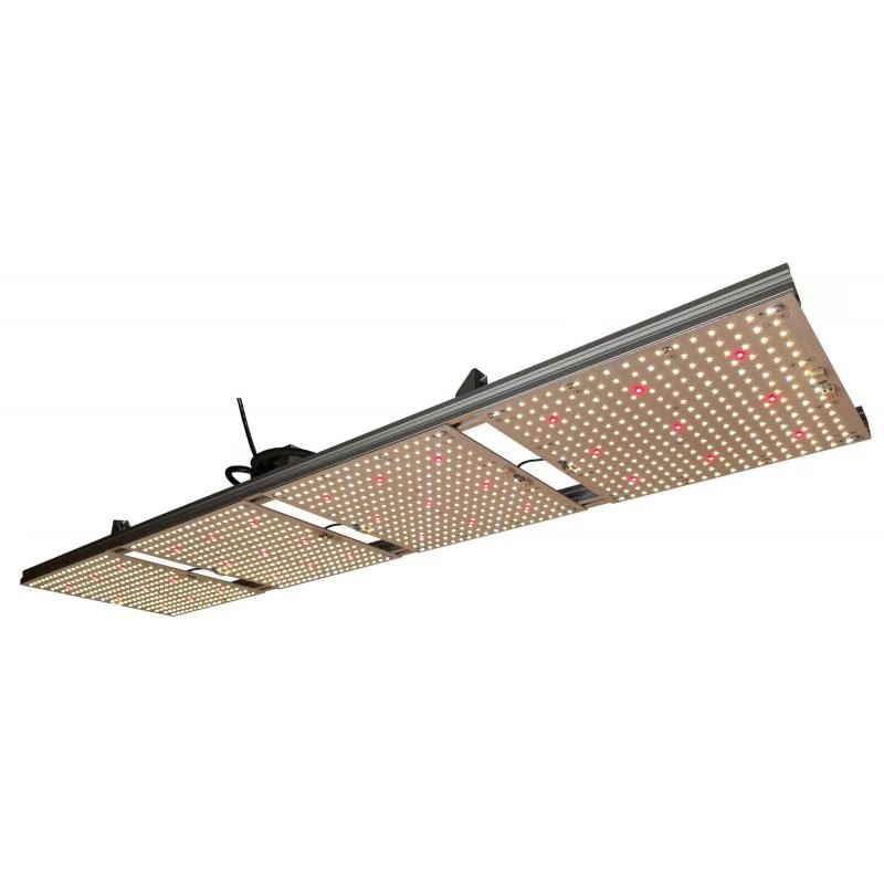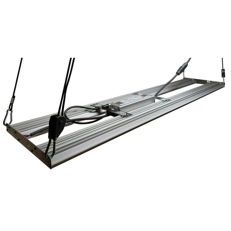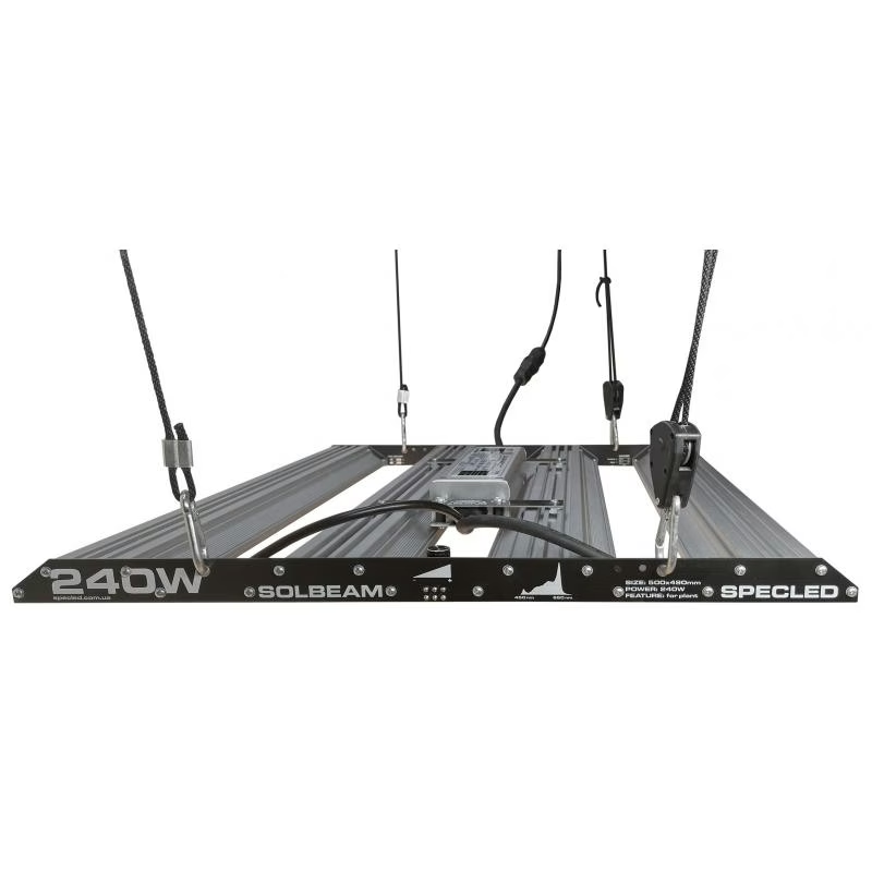
Proper LED cooling is the alpha and omega of any custom lighting project. If the chip overheats, its degradation accelerates tenfold. But how do you know what size aluminum block you need? Buying with a huge margin means overpaying for metal and making the structure heavier (though why not, if you have the option). Buying just enough means risking the LEDs and losing the safety margin in hot summer weather.
We created this tool specifically to save you from guessing and dealing with complex formulas. Below, we will detail the physics of the process and show how an online LED heatsink calculator saves your projects from thermal collapse.
Watts from the Socket Are Not Watts of Heat
When someone first thinks about how to calculate the required heatsink area for an LED module, they usually take the nominal power of the fixture. For example, if you have a 100W Quantum Board, logic suggests you need to dissipate 100W of heat. You go to a forum, find the old rule of thumb "30 square centimeters per Watt," and look for a 3000 cm² profile.
An LED is not an iron (though, as you know, some act like it) and not an incandescent bulb, which converts almost all consumed energy into heat. The job of an LED chip is to generate photons. Modern top-tier diodes (e.g., from Samsung, Cree, Osram, or Seoul Semiconductor) do this brilliantly. The efficiency (WPE — Wall-Plug Efficiency) of good modern chips ranges from 50% to 80%.
What does this mean in practice?
- If you have a quality 100W board with 60% efficiency, 60W of energy goes out as pure light.
- Only the remaining 40W turns into parasitic heat that needs to be dissipated.
Accordingly, the LED heatsink calculation should be based not on 100W, but only on 40W (though realistically, at least 50W with a margin, if you are sure you have a truly high-quality board). To be honest, the old rule of 30 cm² per 1W still works, but only if you build a fixture using modern LEDs like Seoul Semiconductor, Osram, or Cree — then the number 30 drops to 25 cm² per 1W. The difference in dimensions, weight, and cost of the aluminum profile will be significant. The opposite situation occurs with cheap Chinese COB matrices (those very LED irons from AliExpress). Their real efficiency rarely exceeds 20-30%. By plugging 100W into the socket, you get 25W of mediocre light and 75W of concentrated heat capable of warming the room around it.
Why Is It So Important to Maintain Temperature?
The temperature of the chip itself (Tj — Junction Temperature) is the main health indicator of your fixture. Manufacturer datasheets usually indicate an absolute maximum around 105–120 °C. But this is the threshold of death.
The optimal operating temperature of the chip, at which the diode delivers the declared luminous flux and lives the promised 50,000 hours, is 65–85 °C. Of course, the lower, the better: efficiency and lifespan increase.
What happens during overheating:
- Drop in light output. Semiconductor physics is relentless: the hotter the chip, the fewer photons it emits at the same current. Heating a diode from 50 °C to 100 °C can "eat up" to 10% of its brightness. You pay for electricity but get less light.
- Phosphor degradation. White light is produced by coating a blue chip with yellow phosphor. From severe overheating, the phosphor becomes cloudy, cracks, or burns out. The diode starts emitting an ugly "blue" tint and then dies.
- Bonding failure. The thinnest gold wires inside the diode housing can simply tear off due to thermal expansion during constant cycles of severe heating and cooling.
How the Thermal Path Works (And Why Formulas Drive You Crazy)
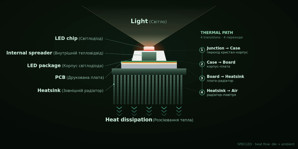
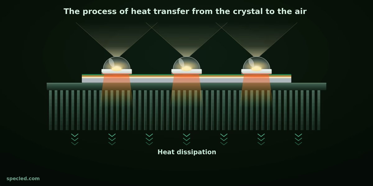
For the heat from the chip (Tj) to reach the surrounding air (Ta), it must overcome several barriers. In thermodynamics, this is described by thermal resistance, measured in Kelvins per Watt (K/W).
The heat path looks like this:
- The chip itself → diode substrate (internal resistance from the datasheet).
- Diode substrate → printed circuit board (resistance of the aluminum MCPCB).
- Printed circuit board → heatsink (resistance of the thermal paste or thermal tape).
- And finally, heatsink → ambient air.
To perform an accurate LED heatsink calculation on paper, you need to subtract the room temperature (e.g., 30 °C) from the target chip temperature (e.g., 80 °C), and then divide this by the number of "thermal" Watts. The resulting value must be stripped of the resistance of the board and thermal paste. Ultimately, you get the required thermal resistance of the heatsink itself (Rhs). And this is what needs to be converted into fin area, taking convection into account.
Sounds complicated? Most users don't want to dive into the thickness of copper foil on a PCB, look up the thermal conductivity of MX-4 paste, and convert K/W into square centimeters.
Using the Online Heatsink Area Calculator
This is exactly why the widget was created. It takes on all the boring and tedious math. How to use it:
- Specify the total electrical power. How many Watts the fixture draws from the socket or driver.
- Select the LED type (or specify the efficiency). The calculator includes approximate presets for popular LEDs and modules. This is a critical step that determines exactly how many Watts will turn into heat.
- Set the ambient temperature. If the lamp hangs in an open room, set it to 25 °C. If it's a closed grow box where air stagnates, it's better to play it safe and set 30–35 °C.
- Specify the desired Tj temperature (LED chip temperature). I recommend aiming for 70–85 °C for the chip itself. If the heatsink is heated to 55 °C, the chip inside the diode will have a quite comfortable 70–75 °C. If possible, you can aim for 45 °C on the heatsink.
By pressing the calculate button, you instantly get the recommended heatsink surface area in square centimeters (cm²). This is the total area of all fins and the base required for stable LED cooling in passive mode (without a fan).
You can switch to "Active" and see how big the difference is if you use a fan. But I am a big opponent of fans: they are highly unreliable, require maintenance and cleaning, and generate noise.
You might also encounter another issue: you have calculated the required heatsink surface area and want to buy a cut piece of a finned heatsink at a flea market, but the seller does not specify its actual surface area. We have solved this problem by creating a widget that helps you calculate the surface area of a finned heatsink based on its profile perimeter or geometric dimensions↗.
RECOMMENDATION: add 10% to the heatsink area obtained from the online calculator for margin and reliability. This also compensates for the "sole" area of the heatsink where the LEDs are mounted. This area is usually located at the bottom, often covered by protective glass or optics, and is ineffective in the LED cooling process.
Three Nuances of Heatsinks to Keep in Mind
Getting a number from the calculator is only half the battle. It is important to correctly choose the aluminum profile itself. Even a huge heatsink of the required area may fail if its geometry is unsuitable for your task.
1. Base Thickness (Spreading Resistance)
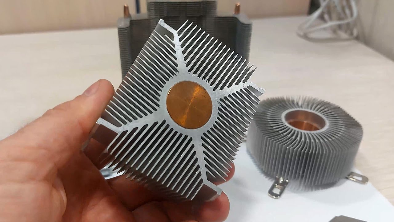
If you are building a powerful fixture (50W and above), heat needs to be quickly distributed from the center of the matrices to the edges of the heatsink. A thin aluminum sheet (2-3 mm) won't handle this. The area right under the diodes will be scorching, while the edges of the heatsink will be cold. For powerful systems, choose an extruded profile with a base thickness of at least 4–6 mm. Copper handles heat distribution much better, but aluminum is significantly cheaper and lighter. For example, old CPU coolers often had a copper slug pressed into the aluminum to speed up heat extraction and transfer to the aluminum.
2. Fin Pitch (Distance Between Fins)
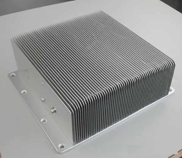
If you plan for passive cooling (without buzzing fans), air must pass freely between the fins via natural convection. If the fins are too close together (distance less than 6-8 mm), hot air will get "stuck" between them, creating a thermal cushion. Heatsinks with very dense and thin finning work perfectly only when paired with active airflow. Such heatsinks are usually very expensive and hard to find. But keep this nuance in mind: it looks great but doesn't work very well.
3. Color Matters (Anodizing)
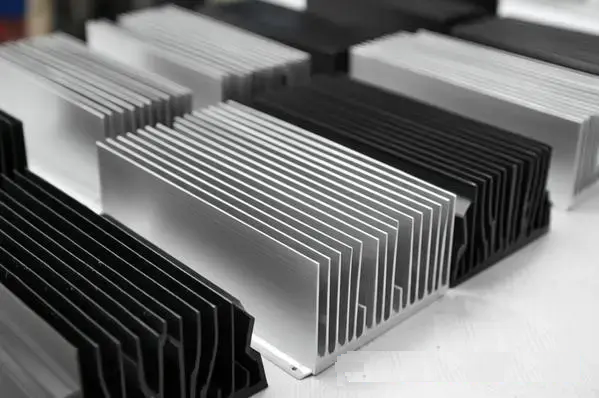
Heat transfers to the air in two ways: convection (heating the passing air) and radiation (infrared radiation). Bare, shiny aluminum radiates heat poorly. However, a profile coated with quality black anodizing dissipates heat more effectively through radiation. In a fully passive mode, a black heatsink, all else being equal, will drop the temperature by another 1-2 degrees, which is a significant bonus for LEDs.
It is better to calculate once than to burn the LEDs three times. The online calculator will help you find the perfect balance between system reliability, weight, and costs. The goal of SPECLED is to simplify the development and construction of LED lamps for plant lighting, as well as to make DIY accessible to everyone.