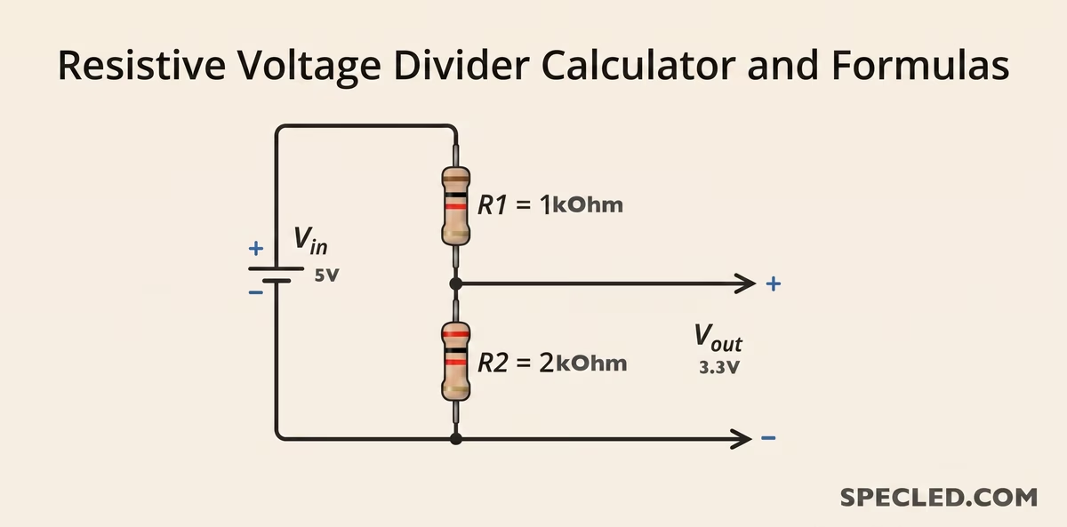
In electronics, one task constantly arises: how to get a lower voltage from a higher one? For example, your main power supply outputs 12 volts, but for the analog-to-digital converter (ADC) of a microcontroller, you strictly need no more than 5 volts. Or perhaps you are trying to connect a 5-volt Arduino board to a modern sensor whose logic operates at the 3.3-volt level.
To solve such problems, engineers long ago invented the voltage divider — a simple yet incredibly important circuit consisting of just two resistors. In this article, we will examine in detail how this circuit works, when it can be used (and when it absolutely cannot), and why our online voltage divider calculator will save you a ton of time.
How Does a Voltage Divider Work?
A classic resistive divider consists of two resistors connected in series (usually denoted as R1 and R2), which are connected to a power source. The junction point between these two resistors forms a midpoint from which the reduced output voltage is taken.
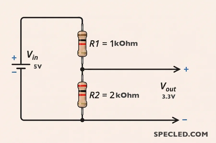
The magic of this circuit lies in Ohm's law. As electrical current passes through the resistors, it creates a voltage drop across them proportional to their resistance.
To decode the color-coding on modern resistors, you can use our calculator↗, as well as understand the logic behind resistor color-band marking.
The Standard Voltage Divider Formula: Manual Calculation
If you need to calculate the voltage divider manually on a piece of paper, the classic formula for calculating the output voltage is applied:
Vout = Vin * R2 / (R1 + R2)
To calculate the resistors for a specific case, when the input voltage is known and the target output voltage of the resistive divider is known, the resistor calculation formulas are used:
Formula for calculating resistor R₁: R1 = R2 * (Vin / Vout - 1)
Formula for calculating resistor R₂: R2 = R1 * Vout / (Vin - Vout)
For all formulas:
- Vin — input source voltage.
- Vout — target output voltage (at the midpoint).
- R1 — upper resistor, connected to the positive supply.
- R2 — lower resistor, connected to ground (GND).
Engineers usually first select one resistor based on the required current (for example, taking a common 10 kOhm value), and the second is calculated using the formula for resistor R₂.
At first glance, the math is simple. But in practice, developers often have to solve the reverse problem: the output voltage is already known, and you need to select the values of R1 and R2 from standard series (like E12 or E24) to get the desired value. Calculating this mentally with fractions is extremely inconvenient. This is exactly why our voltage divider calculator was created in an interactive widget format — simply enter the desired parameters, and the system will instantly select the required standard resistor values and show the exact voltage at the output of the resistive divider.
Practical Applications for a Voltage Divider Calculator
Dividers are most often used for logic level matching. Below is a handy table with standard resistor values for the most common scenarios in DIY electronics and Arduino projects.
| Input Voltage | Target Output | Optimal R1 | Optimal R2 | Actual Vout |
|---|---|---|---|---|
| 5.0 V (Arduino Uno) | ~3.3 V (ESP8266, Sensors) | 1.8 kOhm | 3.3 kOhm | 3.23 V |
| 5.0 V | ~3.3 V (Alternative) | 10 kOhm | 20 kOhm | 3.33 V |
| 12.0 V (Car battery) | ~5.0 V (ADC input) | 15 kOhm | 8.2 kOhm | 5.12 V |
| 24.0 V (Industrial) | ~3.3 V (Logic) | 68 kOhm | 10 kOhm | 3.07 V |
| 3.3 V | ~1.8 V | 10 kOhm | 12 kOhm | 1.80 V |
Note: The resistances in the table are selected to minimize leakage currents while ensuring a stable signal.
Loaded Voltage Divider: A Common Beginner's Mistake
The most important rule that every beginner electronics enthusiast should remember: a resistive voltage divider cannot be used as a standalone power supply for a heavy load. Unless, of course, you are crazy or perhaps you simultaneously need a powerful electric heater made of resistors.
Why? As soon as you connect any load (e.g., an LED, a motor, or a microchip) to the midpoint, its own internal resistance Rload becomes connected in parallel to the lower resistor R2. This instantly changes the total resistance of the lower arm of the circuit, and your carefully calculated output voltage drops.
At the same time, a large current for the heavy load must flow through the upper resistor R1, which requires the use of high-power resistors in metal cases with a resistance of tenths of an Ohm. You can do this, but the resistors will "eat up" a huge part of the power and effectively heat the room they are in.
The golden rule of engineering: The resistance of resistor R2 must be at least 10 times smaller than the resistance of the connected load. Only in this case will the voltage drop error be acceptable.
When used properly, a resistive voltage divider is an indispensable tool in electronics, allowing you to interface different circuits, implement feedback, set a reference voltage, and much more. Typically, resistive dividers are designed for very low currents and are assembled from SMD resistors with low power ratings and small dimensions. For the convenience of our resource's users, we have created an interactive and engaging widget↗ that will help you understand the numeric and alphanumeric markings of SMD resistors according to the EIA-96 standard.
If you need to power a "power-hungry" component, a divider will not work — most of the energy will simply dissipate as heat on resistor R1. For such purposes, you should use linear voltage regulators (like LDOs) or switching DC-DC converters.
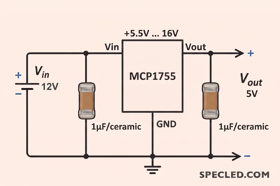
However, for measuring circuits where large currents do not flow, reading thermistors, photoresistors, and transmitting digital signals, the resistive divider remains an ideal tool.
Why Bookmark Our Resistor Divider Calculator?
When you are sitting with a soldering iron or routing a printed circuit board in a CAD program, there is no time to be distracted by cumbersome formulas. Our specialized tool allows you to:
- Instantly find Vout, knowing the resistance of the arms.
- Find the required resistance of R1 or R2 for a specific task.
- Avoid mistakes when choosing multipliers (kOhm, MOhm).
- Calculate the necessary power rating for resistors R1 and R2.
- Find out the maximum load current for the resistive divider.
- In case of incorrect data entry, the widget will instantly snap you out of the "matrix" back into the real world and show a warning! For example, if the calculated power of resistors R1 and R2 is too high.
By using our online tool, you reduce the probability of error to zero. Bookmark this page so that a reliable resistor divider calculator is always at your fingertips!