There are two common ways to select a wire size. The first is the "looks thick enough, it'll do" approach. The second is to open a wire gauge calculator, enter the current, and get a number. Both methods can yield the wrong answer if one crucial detail is ignored: the wire cross-section is selected based not on one criterion, but two simultaneously, and depending on the situation, either one can be the limiting factor.
Our cable size calculator evaluates both criteria simultaneously and checks the result against several additional standard requirements. Let's break down how to calculate correctly, the differences between AWG, SWG, and square millimeters, and why a 12V or 24V LED assembly requires a thicker wire than the same load in a mains voltage network.
Two Criteria for Wire Size Selection
Calculating the cable cross-section by power or current is only half the task. There are two independent requirements, and the wire must satisfy both. Additionally, a wire should always be chosen with a safety margin. First and foremost, this is about your safety; a wire that is too thin can lead to a real fire.
Criterion One: Heating (Ampacity)
As current flows through a conductor, it generates heat because any conductor, except a superconductor, has electrical resistance. The thinner the core, the higher the resistance and the greater the heating. If the limit is exceeded, the insulation will begin to degrade — first losing elasticity, then cracking, eventually leading to a short circuit and fire.
Hence the concept of continuous current-carrying capacity (ampacity): the maximum current at which the wire will not overheat under specified conditions. For copper with 70 °C PVC insulation, clipped directly to a wall at an ambient temperature of 30 °C, the standard gives 19.5 amps for 1.5 mm², 27 for 2.5 mm², and 36 for 4 mm². These values are from Table 2 of DIN VDE 0298-4 for two loaded conductors — meaning this is the absolute maximum without any safety margin. Operating continuously at this limit is not recommended.
An important detail: the standard doesn't have a single "permissible current" column. There are several, and they differ by up to a third. There are separate columns for two loaded conductors (DC and single-phase AC) and for three (three-phase), and separate columns for each installation method. The calculator automatically selects the correct column, but if you calculate manually using a table from the internet, make sure you are reading the right one.
Criterion Two: Voltage Drop
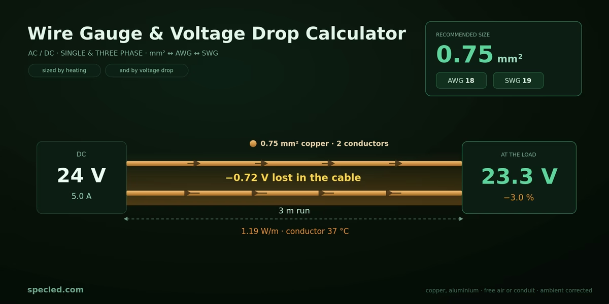
A wire is a resistor, and some voltage is lost across it. Less voltage reaches the load than what left the source. For DC and single-phase AC networks, the formula is:
ΔU = 2 × I × L × ρ₁ / S
where I is the current in amps, L is the one-way line length in meters, S is the cross-section in mm², and ρ₁ is the resistivity of the conductor. The multiplier of 2 appears because the current travels to the load and returns — the actual conductor length is twice the distance.
It's easy to make a 25% error here. Handbooks usually provide the resistivity of copper at 20 °C: 0.0172 Ω·mm²/m. However, a wire under load is not cold, but hot, and the resistance of copper increases by about 0.4% for every degree. Therefore, HD 60364-5-52 (Annex G) mandates calculating the voltage drop using the resistance at operating temperature: ρ₁ = 0.0225 Ω·mm²/m for copper and 0.036 for aluminum — this is the value at 20 °C multiplied by 1.25. If you calculate based on a cold wire, the voltage drop will be 25–30% less than reality, and the calculator will recommend a wire one size thinner than required.
For alternating current, two more factors appear in the formula — the power factor and the line reactance:
ΔU = 2 × I × L × (ρ₁/S × cos φ + λ × sin φ)
where λ ≈ 0.08 mΩ/m. On thin wires, the reactive component is negligible because the active resistance is an order of magnitude higher. However, for 25 mm² and above, it alters the result, and calculating "by resistance only" underestimates the drop by about a third.
For a three-phase network, the square root of three replaces the multiplier of two, and the drop is calculated using the line-to-line voltage:
ΔU = √3 × I × L × (ρ₁/S × cos φ + λ × sin φ)
Voltage drop is evaluated as a percentage of the nominal voltage. For LED assemblies, it is customary to stay within 3%, while 5% is acceptable for mains wiring. In Germany, for residential buildings, DIN 18015-1 requires no more than 3% from the meter to the consumer.
Why Low-Voltage Circuits Are Different
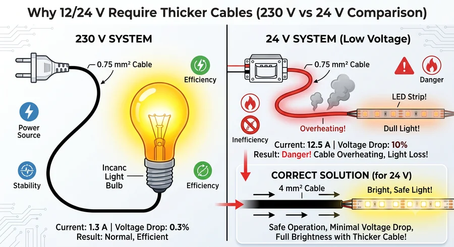
Here is the catch! Standard calculators only consider heating and give the correct answer for a 230V mains network. But for 12V or 24V, that answer can be dangerously optimistic.
The issue is that voltage drop is measured in volts, but its permissibility is in percentages. A loss of 0.7 volts at 230 volts is 0.3%, which nobody will notice. That same loss at 24 volts is 3%, which is the limit. And at 12 volts, it's 6%, twice the norm.
Let's look at the numbers. A load of 5 amps, 10 meters long, copper, 40 °C temperature, installed in a conduit, 25% margin, and an allowable drop of 3%:
- Based on heating, 1.0 mm² is sufficient. At 40 °C, the correction factor is 0.87, and this core can handle 8.7 amps — leaving plenty of margin for the required 6.25 A.
- However, based on voltage drop at 24 volts, you will need 4 mm², which is four times the cross-section.
What happens if you install 0.75 mm², as an "eyeball" estimate might suggest? The drop will be 3.0 volts — that's 12.5% instead of the allowable 3%. The LEDs will receive 21 volts instead of 24, and 15 watts will be dissipated as heat on the wire, essentially acting like underfloor heating. With the correct 4 mm² cross-section, the drop falls to 0.56 volts, or 2.3%, and the losses to 2.8 watts.
| Cross-section | Iz at 40 °C in conduit | Drop at 24 V | Power loss in wire |
|---|---|---|---|
| 0.75 mm² | 5.2 A | 3.00 V — 12.5% | 15.0 W |
| 1.0 mm² | 8.7 A | 2.25 V — 9.4% | 11.3 W |
| 1.5 mm² | 14.4 A | 1.50 V — 6.3% | 7.5 W |
| 2.5 mm² | 20.0 A | 0.90 V — 3.8% | 4.5 W |
| 4.0 mm² | 26.1 A | 0.56 V — 2.3% | 2.8 W |
Pay attention to the first and third columns: all five options, starting from 1.0 mm², pass the heating criteria, but only the last one passes the voltage drop criteria. This is exactly what "sizing by the greater of two criteria" means.
The rule is simple: the lower the voltage and the longer the line, the more likely the voltage drop will be the limiting factor, not heating. For a 230V network on short runs, it's usually the opposite.
Calculating Cable Size by Power
Often, the initial data is provided not in amps, but in watts: the power of the luminaire, heater, or the entire assembly is known. Converting one to the other is simple.
For DC: I = P / U. A 300W luminaire at 24 volts consumes 12.5 amps. The exact same luminaire powered from 230 volts consumes only 1.3 amps.
For a single-phase AC network, the power factor must be considered: I = P / (U × cos φ). For a purely resistive load, cos φ equals 1, and the formula simplifies to the previous one.
This, incidentally, shows why low-voltage assemblies require thick wires: at the same power, the current is inversely proportional to the voltage, and the wire heating increases as the square of the current. Switching from 24 to 48 volts halves the current and quarters the wire losses. By the way, this is one of the reasons why industrial solar panels operate at 48 volts.
For a three-phase network, the formula is different: I = P / (√3 × U × cos φ), where U is the line-to-line voltage, and cos φ is the load's power factor. For resistive loads, it is close to 1; for motors and switched-mode power supplies, it can be 0.7–0.95, and this must be taken into account.
A separate warning regarding LED assemblies. The power at the driver input and the output power are different things. A driver with 90% efficiency at 100W output power will consume about 111W from the mains. The input line current must be calculated based on the consumed power, not the nominal rating of the luminaire. Our circuit breaker sizing calculator↗ will help you choose the right parameters to protect your line from overload.
What Else Affects Ampacity
Tabulated values are given for specific conditions, and real-world conditions almost always differ. The standard is designed this way: the base current It is taken from the table and then multiplied by correction factors. The final result is denoted as Iz:
Iz = It × f1 × f2 × f4
- Installation method. This is not a correction factor, but a separate column in the table. A wire in free air is cooled by convection; the same wire in a conduit cools much worse, and one embedded in a thermally insulated wall cools very poorly. For 2.5 mm², the standard allows 30 A in free air, 27 A clipped directly to a wall, 23 A in a conduit, and 18.5 A in an insulated wall. The variation is almost 1.5 times, and taking an "average factor of 0.72" is incorrect: the ratio changes for larger cross-sections.
- Ambient temperature, factor f1. Tables are compiled for 30 °C. In a grow tent, enclosed distribution board, or near drivers, the temperature can reach 45–50 °C, and the allowable current drops significantly. For PVC insulation, the factor is 0.87 at 40 °C, 0.79 at 45 °C, 0.71 at 50 °C, and 0.61 at 55 °C. This means a 2.5 mm² wire rated for 27 amps will only handle 16.5 A in a panel at 55 °C.
- Grouping, factor f2. Cables laid side-by-side heat each other. For a bundle, this factor is 0.80 for two circuits, 0.70 for three, 0.65 for four, and 0.48 for ten. A separate scenario is a cable on a drum: a coiled reel dissipates almost no heat, and the standard assigns 0.80 for one layer, 0.61 for two, 0.49 for three, and only 0.38 for five layers. If you power a grow tent through an unspooled extension reel, you have lost more than half the allowable current capacity.
- Harmonics, factor f4. This only applies to three-phase lines with pulsed loads, detailed below.
- Material. Aluminum has a resistivity of 0.036 compared to 0.0225 for copper — 1.6 times higher. Therefore, for an equal cross-section, the voltage drop is proportionally greater, and the allowable current is about a quarter lower. Plus a restriction: in fixed wiring, aluminum is only permitted starting from 16 mm². It is practically never used for low-voltage setups.
- Design margin. A wire should not operate right at the edge of its allowable current — a 20–25% overhead is typically added. This is not a requirement of the standard, but good engineering practice, and it's justified: the load might increase, conditions may worsen, and insulation ages faster the hotter it runs.
AWG, SWG, and mm²: How to Convert Between Them
Three designation systems coexist, which is a constant source of confusion. Wire on AliExpress is sold in AWG, in Europe in square millimeters, and older British documentation uses SWG.
- AWG (American Wire Gauge) is calculated using the formula: diameter in millimeters equals 0.127 × 92^((36−n)/39), where n is the gauge number. The logic is reversed: the larger the number, the thinner the wire. AWG 10 is thicker than AWG 20.
- SWG (British Standard Wire Gauge) is a historical table compiled empirically. Conversion can only be done using a reference table; there is no conversion formula.
- Square millimeters (mm²) refers to the cross-sectional area of the conductor, the most intuitive measurement. The diameter is derived from it as the square root of 4S/π.
There is a nuance in the conversion principle itself. Exact matches between systems rarely exist, so rounding can be done in two directions — to the nearest gauge or to the nearest non-smaller gauge. The calculator always rounds in the latter direction: it will never suggest a wire thinner than calculated. Therefore, its SWG value may differ by one from tables that state the "nearest" value.
AWG to mm² and SWG Equivalency Table
Ampacity (Iz) is indicated for copper with 70 °C PVC insulation at an ambient temperature of 30 °C, for two loaded conductors, with no grouping. Power is calculated as the product of the allowable current and voltage — for a quick estimate when calculating cable size by power; it does not account for voltage drop.
| mm² | AWG | SWG | Diameter, mm | Iz open on wall | Iz in conduit | Power at 12 V | Power at 230 V |
|---|---|---|---|---|---|---|---|
| 0.5* | 20 | 21 | 0.80 | 3 A | 3 A | 36 W | 0.7 kW |
| 0.75* | 18 | 19 | 0.98 | 6 A | 6 A | 72 W | 1.4 kW |
| 1.0* | 17 | 18 | 1.13 | 10 A | 10 A | 120 W | 2.3 kW |
| 1.5 | 15 | 17 | 1.38 | 19.5 A | 16.5 A | 234 W | 4.5 kW |
| 2.5 | 13 | 15 | 1.78 | 27 A | 23 A | 324 W | 6.2 kW |
| 4.0 | 11 | 13 | 2.26 | 36 A | 30 A | 432 W | 8.3 kW |
| 6.0 | 9 | 11 | 2.76 | 46 A | 38 A | 552 W | 10.6 kW |
| 10 | 7 | 9 | 3.57 | 63 A | 52 A | 756 W | 14.5 kW |
| 16 | 5 | 6 | 4.51 | 85 A | 69 A | 1.0 kW | 19.6 kW |
| 25 | 3 | 4 | 5.64 | 112 A | 90 A | 1.3 kW | 25.8 kW |
| 35 | 1 | 2 | 6.68 | 138 A | 111 A | 1.7 kW | 31.7 kW |
| 50 | 0 | 0 | 7.98 | 168 A | 133 A | 2.0 kW | 38.6 kW |
* Cross-sections thinner than 1.5 mm² do not exist in the tables for fixed wiring — the standard simply does not permit them. The values for 0.5, 0.75, and 1.0 mm² are taken from a separate table for flexible cables and cords of household appliances, and they are notably lower than commonly believed. The calculator tags such cross-sections with a "flexible cable" badge so the result isn't mistakenly applied to in-wall wiring.
And once again about approximations: the closest gauge to 1.5 mm² is AWG 15, but its actual cross-section is 1.65 mm². The more common AWG 16 provides 1.31 mm², which is less than 1.5 squares. When replacing European wire with American wire, this must be taken into account: a 10–15% difference in cross-section directly translates into the same difference in voltage drop.
The Neutral Wire in a Three-Phase Network
This is a distinct topic where intuition fails most frequently.
The classic rule states: with a balanced load, the currents of the three phases are shifted by 120 degrees, sum vectorially to nearly zero, and the neutral can be made thinner than the phase conductors. This practice was followed for decades.
The problem is that this rule only applies to linear loads — resistive heaters, incandescent lamps, motors. However, switched-mode power supplies, which include all LED drivers, behave differently. They draw current not as a sine wave, but in short pulses, generating harmonics that are multiples of three: the third, ninth, and fifteenth.
The key point: these harmonics in all three phases are in phase with each other. They do not cancel out in the neutral; they sum up arithmetically. The neutral current is approximately equal to three times the third harmonic current, and if its share exceeds a third, the neutral ends up more heavily loaded than any of the phases — up to 1.73 times the phase current.
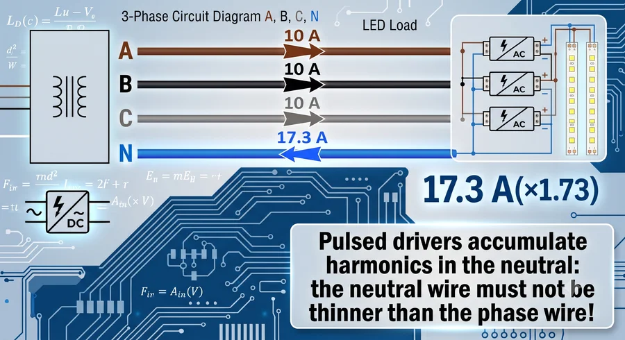
The standard addresses this with four bands based on the third harmonic content. In the lower two, the cross-section is sized according to the phase current; in the upper two, it is sized by the neutral current:
| 3rd Harmonic Content | Factor f4 | Sizing Based On | Typical Load |
|---|---|---|---|
| 0–15% | 1.00 | phase current | Resistive heaters, motors, incandescent lamps |
| 15–33% | 0.86 | phase current | drivers with active PFC, EN 61000-3-2 compliant equipment |
| 33–45% | 0.86 | neutral current | mixed loads, numerous power supplies |
| above 45% | 1.00 | neutral current | drivers without power factor correction |
The practical takeaway for an installation with LED drivers: the neutral wire should not be thinner than the phase wire, and in tightly bundled routing, it should be one size thicker. Another consequence that is usually overlooked: if the neutral is heating up, the allowable power capacity of the entire line is determined by it. The calculator accounts for this — when selecting the "LED without PFC" band, the permissible load drops by about half compared to a linear load of the same cross-section.
Short-Circuit Withstand Capability
The two criteria above deal with normal operating conditions. There is also an emergency mode, which must be verified separately.
During a short circuit, the current is two to three orders of magnitude higher than the operating current, but it lasts only a fraction of a second. The heat simply doesn't have time to dissipate into the insulation and the environment — it all remains in the copper. Such a process is called adiabatic, and it yields a very straightforward condition.
- Short-circuit withstand — the ability of the conductor to survive the short-circuit current for the duration it takes for the protection device to clear the fault, without destroying the insulation. This is verified by a separate formula and has nothing to do with heating in normal mode: a wire can be completely cold at operating current yet fail to withstand a short circuit.
- Adiabatic minimum — the minimum cross-section derived from this condition: S ≥ √(I²t) / k, where I is the RMS value of the short-circuit current in amps, t is the disconnection time in seconds, and k is the material and insulation factor. For PVC copper, it is 115; for PVC aluminum, 76; for XLPE copper, 143. Example: 6 kA and 0.4 seconds give 6000 × √0.4 / 115 = 33 mm².
- Limit time — the same formula, solved in reverse: how many seconds the chosen cross-section will survive at a given SC current, t = (k × S / I)². This value is used to compare with the actual characteristic of the protective device. If the limit time is less than the breaker's tripping time, the cross-section must be increased.
It's easy to over-engineer this to the point of absurdity, so it's vital to understand where the time value comes from. The flat 0.1 or 0.4 seconds is not the SC disconnection time, but the required automatic disconnection time for an earth fault. During a true short circuit, the breaker enters its electromagnetic tripping zone and clears the fault in 5–10 milliseconds. The difference in the result is massive: at 1 kA and 0.1 s, the adiabatic equation demands 2.75 mm², but at the same 1 kA and 0.01 s, it requires only 0.87 mm².
That's why the SC current field in the calculator is empty by default: until you fill it, the check is skipped, avoiding interference when designing low-voltage lines where the SC current is limited by the driver itself. As soon as you enter a value, the criterion is included in the selection process alongside heating and voltage drop.
Calculator Terminology Glossary
The widget uses designations from the standards, not colloquial terms. Here is a brief explanation to avoid guesswork.
| Designation | Meaning |
|---|---|
| Ib | design load current — what actually flows through the line in normal operation |
| It | tabulated current: the base value from the standard's table, before any correction factors |
| Iz | continuous current-carrying capacity (ampacity) after all corrections, Iz = It × f1 × f2 × f4. The safety condition is: Ib ≤ Iz |
| f1 | correction factor for ambient temperatures other than 30 °C |
| f2 | correction factor for grouping: bundle, layer, or drum |
| f4 | correction factor for harmonics in a three-phase circuit |
| A2 / B2 / C / E | reference installation methods: in an insulated wall, in conduit or trunking, clipped direct to a wall, free in air |
| ρ₁ | resistivity at operating temperature: 0.0225 for copper, 0.036 for aluminum |
| cos φ | load power factor; not applicable for direct current |
| Short-circuit withstand | verification of the conductor against the short-circuit current during the protection device's operating time |
| Adiabatic minimum | the smallest cross-section based on the condition S ≥ √(I²t)/k |
| Limit time | how long the chosen cross-section will survive the given SC current, t = (k·S/I)² |
| Design margin | a voluntary designer's safety margin above Ib; does not affect the standard's requirements |
Standards Behind the Calculation
All calculations in the calculator are performed according to current European Union standards, not averaged internet tables. European standards are mutually harmonized: an international IEC standard is adopted as a European HD document, which is then implemented nationally as DIN VDE in Germany, BS 7671 in the UK, and NF C 15-100 in France. It is the same calculation with national modifications.
- IEC 60364-5-52 = HD 60364-5-52 = DIN VDE 0298-4 and DIN VDE 0100-520 — allowable currents, installation methods, correction factors for temperature, grouping, and harmonics. Tabulated values are taken from DIN VDE 0298-4 edition 2023-06: Table 2 for fixed wiring, Table 11 for flexible cables, Tables 17, 22, and 28 for correction factors, Annex B.1 for harmonics.
- HD 60364-5-52, Annex G — voltage drop calculation using resistance at operating temperature and accounting for the reactive component.
- IEC 60364-4-43 = HD 60364-4-43 = DIN VDE 0100-430, Table 43.1 — verification for thermal withstand under short circuit and k-factors.
- DIN 18015-1 — 3% voltage drop limit for residential buildings.
The designations for installation methods A2, B2, C, and E in the widget are the very same reference Verlegearten found in the original standard's table. This way, you can cross-reference any figure from the calculator with a printed handbook without guessing what was meant.
A mandatory disclaimer: this calculation remains a reference tool. National annexes to European standards vary, local regulations apply to fixed electrical wiring, and electrical installation designs must be carried out by a licensed professional.
How to Use the Calculator
The widget above calculates both primary criteria simultaneously, displays the result based on the greater of the two, and provides a separate block showing which standard requirements are met and which are not. The interface is available in six languages, switchable via the buttons in the top right corner.
What to Enter
- Load current Ib and line length. The length is specified one-way — the calculator accounts for the return wire automatically. Below the current slider, the design current including the safety margin is displayed; this is the value actually used for sizing.
- Voltage. A slider from 1 to 400 volts, plus preset buttons: 5, 12, 24, 36, 48, 110, 230, and 400.
- Current type and material. Direct current, single-phase AC, or three-phase AC; copper or aluminum. For three phases, the calculator automatically shifts to the three loaded conductors column and applies the square root of three formula.
- Power factor cos φ. This block is only active for alternating current. Along with it, line reactance is factored into the calculation.
- Installation method. Four reference options — from an insulated wall to free air. This is the most underestimated parameter: the allowable current differs by almost 1.5 times between the extreme options.
- Ambient temperature. The current value of the f1 factor is displayed below the slider, illustrating how the tabulated current is modified.
- Grouping. Bundled, in a single layer, or on a drum. For the first two, you specify the number of adjacent circuits; for the drum, the number of layers. The f2 value is displayed right there.
- Design margin and allowable drop. Defaults are 25% and 3% — standard engineering practice for LED assemblies.
- Short-circuit withstand. Two fields: short-circuit current in kiloamps and disconnection time in seconds, with presets. As long as the current field is empty, the check is bypassed. Once you fill it in, the adiabatic minimum cross-section joins the sizing process alongside the other criteria.
- Neutral wire N. This block activates when three phases are selected. The switch sets the third harmonic content — from a linear load to drivers without PFC. The selection affects the neutral cross-section, the f4 factor, and the allowable power of the line.
What You Will Get
- Cross-section simultaneously in three systems — mm², AWG, and SWG. If the result is thinner than 1.5 mm², a "flexible cable" badge will appear next to it: this is a reminder that such a size is not suitable for fixed wiring.
- Permissible load in watts or kilowatts — how much this line can handle based on both heating and voltage drop under the chosen conditions.
- The equation Iz = It × f1 × f2 × f4 populated with numbers. This is crucial for verification: instead of just a final number from a black box, you see the entire calculation path from the standard's table to the result and can verify each multiplier.
- Voltage drop in volts and percentages, end-of-line voltage, power losses, heat dissipation per meter, ampacity Iz, and conductor temperature. In three-phase mode, losses and temperature are calculated based on the most heavily loaded conductor — with a high harmonic share, this is the neutral, not the phase.
- "Compliance Check" block — four to six rows with checkmarks: heating, voltage drop, conductor temperature, minimum size, SC withstand, and aluminum restriction. An exclamation mark indicates a warning; a cross means the requirement is not met.
- "Custom size" slider — allows you to deviate from the calculated value and see what happens with adjacent nominal sizes. A reset button appears automatically.
- The schematic diagram at the top dynamically updates with the parameters: wire thickness grows with the cross-section, a third wire appears when switching to three phases, and the color turns red when overloaded.
At the bottom, there is a standalone converter block: enter a value in any of the three fields, and the other two will recalculate automatically. It also displays the conductor diameter, the nearest standard cross-section, the ampacity for two installation methods, and the copper resistance per meter. If the entered cross-section falls outside the standard's table, a dash is shown instead of current — allowable current cannot be extrapolated, as it does not scale linearly with area.
Common Mistakes
- Calculating based on heating only. The most common error. It works for short runs in a mains network but fails on everything else.
- Forgetting that the length is doubled. The voltage drop calculation involves the full current path — to the load and back. If you only use the distance, your error will be exactly a factor of two.
- Calculating voltage drop on a cold wire. Copper resistance at 20 °C and at an operating 70 °C differs by a quarter. The standard requires calculating based on operating temperature.
- Using tabulated current without correction factors. The tables are for 30 °C, single routing, and a specific installation method. In a hot panel with wires in a bundle, the actual ampacity could be half as much.
- Reading the wrong column. A three-phase line requires the "three loaded conductors" column, which is about ten percent lower. This is a silent error that only manifests through cable heating.
- Powering a load through an unspooled cable drum. Five layers on a reel mean a coefficient of 0.38; thus, only slightly more than a third of the allowable current capacity remains.
- Sizing the circuit breaker for the load, not the cable. A circuit breaker protects the wire from overload, not the appliance. If you install a 1.5 mm² wire with a 25-amp breaker, the wire will burn up before the breaker trips. I've only touched the surface here; selecting a circuit breaker is actually a very complex topic where numerous parameters must be considered beyond just current. This deserves a separate article.
- Assuming a stranded wire is equivalent to a solid wire of the same diameter. In a flexible cable, the core consists of many thin strands with air gaps between them. The actual copper cross-section is smaller than the outer diameter might suggest.
Conclusion
- Wire size is selected based on the greater of two criteria — heating and voltage drop. Neither can be ignored, and for fixed wiring, short-circuit withstand capability is also added.
- For low-voltage circuits, voltage drop is almost always the deciding factor, not heating. The lower the voltage and the longer the line, the greater the divergence between the criteria.
- Voltage drop is calculated using resistance at operating temperature: 0.0225 Ω·mm²/m for copper. Calculating with a cold wire underestimates the result by a quarter.
- The tabulated ampacity requires correction factors for ambient temperature and grouping, and the installation method dictates which table column to use entirely. In a hot panel with a bundle of cables, the allowable current halves.
- When converting AWG to mm², the equivalence is approximate — the nearest gauge can differ from the metric nominal by 10–15%.
- In a three-phase network with LED drivers, the neutral wire should be no thinner than the phase wires due to harmonics that are multiples of three, and it is the neutral that limits the power of the entire line.
- All figures in the calculator are drawn from current EU standards — IEC/HD 60364-5-52, DIN VDE 0298-4, DIN VDE 0100-520 and 0100-430, DIN 18015-1 — not from averaged tables.
- And most importantly: any calculation serves as a reference. Local regulations apply to fixed electrical wiring, and when in doubt, it is better to choose one size larger — the price difference is insignificant compared to the consequences of a mistake.