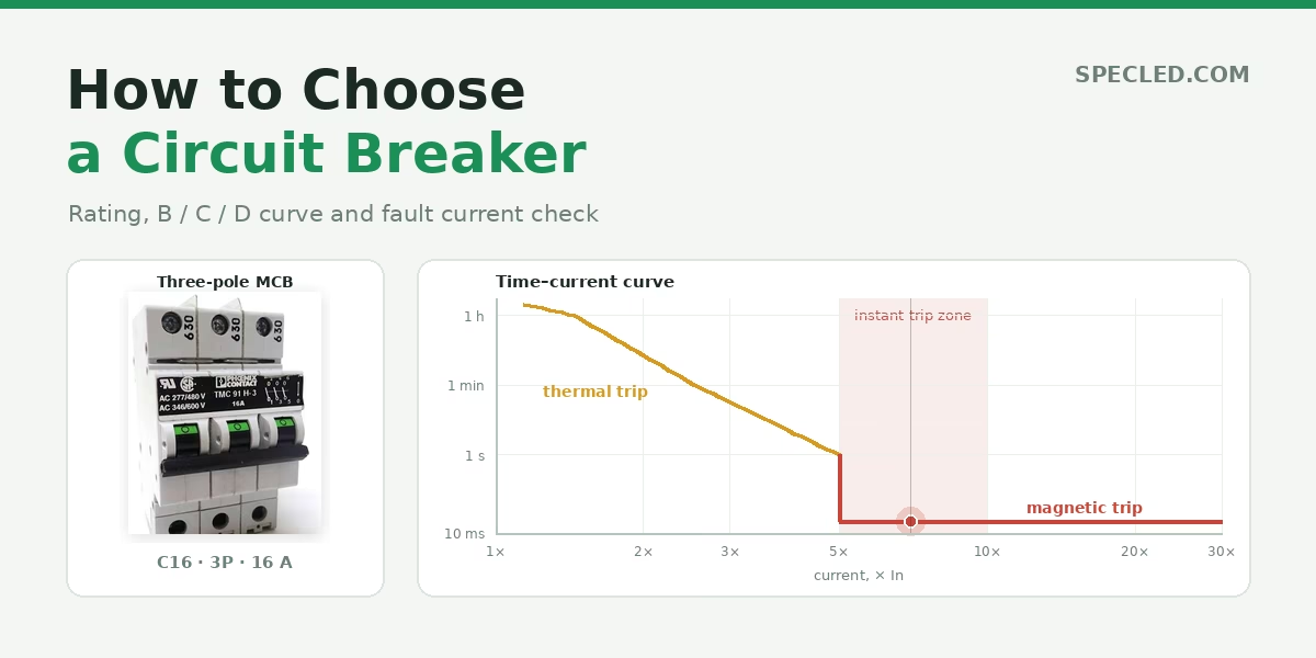
Perhaps the most common reasoning for choosing a circuit breaker sounds like this: a 10-ampere load means we install a 16-amp breaker, just to have a safety margin. This method is straightforward, fast, and almost always wrong. That is because a circuit breaker protects the cable, not the appliance, and its rating is selected not based on the load, but on what is routed inside the wall, on the wall, or above the ceiling.
Let us examine how to select a miniature circuit breaker (MCB) correctly: the rule used to calculate its nominal current rating, how B, C, and D tripping characteristics differ, why line length can turn a fully functional breaker into a useless one, and what checks professionals perform beyond a simple ampere comparison.
The Golden Rule: The Breaker Protects the Cable
This is the core principle from which everything else follows. A circuit breaker does not protect your refrigerator or save your light fixture—it prevents the cable from overheating and catching fire.
The logic is as follows: every cable has a maximum current-carrying capacity at which its insulation remains undamaged. If the current exceeds this threshold for an extended period, the insulation loses elasticity, cracks, and eventually leads to a short circuit and conductor failure inside the wall—or, in the worst-case scenario, an electrical fire.
The breaker's job is to disconnect the line before the cable reaches that state. Therefore, the breaker's nominal rating must be selected so that it trips before the cable degrades. This gives us the primary coordination condition:
I_b ≤ I_n ≤ I_z
The design current of the load (I_b) must not exceed the nominal rating of the breaker (I_n), otherwise it will trip during normal operation. Furthermore, the breaker rating must not exceed the continuous current-carrying capacity of the cable (I_z), otherwise the breaker will fail to notice that the conductor is burning.
This leads to a practical conclusion that reverses the conventional sequence of actions: first, select the cable for the load; then, select the breaker for the cable. Never the other way around. You can use our cable cross-section calculator↗ based on power and current.
What Happens When the Rule Is Violated
Imagine a 1.5 mm² cable with an allowable current-carrying capacity of 19.5 amperes protected by a 25 A breaker. Formally, everything works: the socket is live, the lights are on. However, if a 22-ampere load is plugged into the line, the breaker will not detect an issue—22 is less than 25, so everything appears fine to it. Meanwhile, the cable is running at a 13% overload and slowly degrading. Within a year or two, the insulation will begin to crumble.
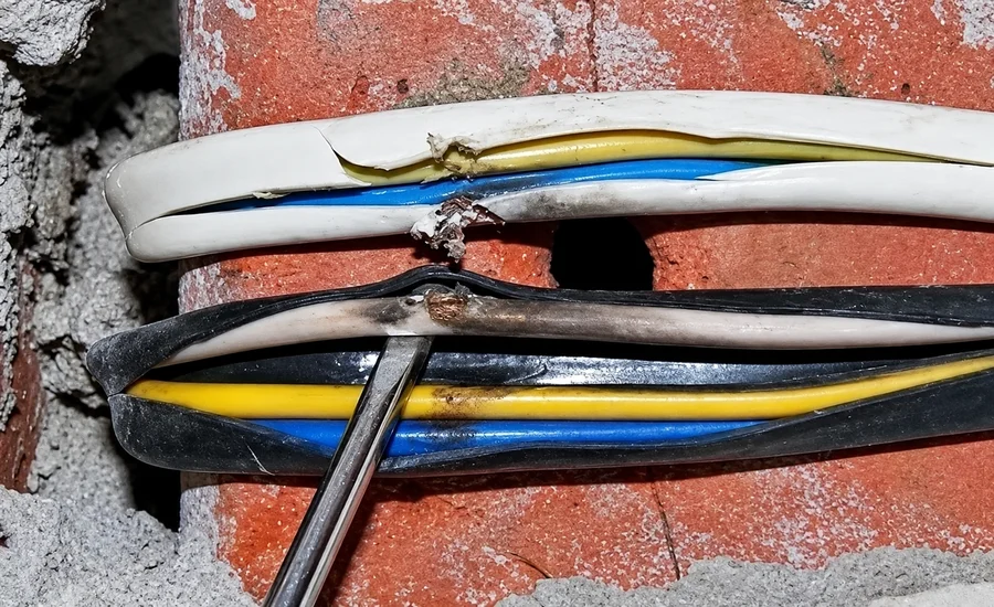 Charred wire inside a wall resulting from line overheating
The reverse situation also occurs: a 4 mm² cable paired with a 10-ampere breaker. There is no safety hazard here, but it makes little economic sense—you overpaid for copper while restricting the circuit to ten amperes. Still, this remains the safest possible arrangement.
B, C, and D Characteristics: What Is the Difference?
The letter preceding the nominal current is not a manufacturer code; it indicates the type of time-current characteristic curve. It defines the level of overcurrent required to trip the magnetic instantaneous release.
According to the IEC 60898-1 standard, three primary types are defined:
- Type B Characteristic — instantaneous tripping between 3 and 5 times rated current ($In$). This is the most sensitive curve. For a B16 breaker, this range is between 48 and 80 amperes: below 48 A, it will not trip instantaneously; above 80 A, instantaneous tripping is guaranteed.
- Type C Characteristic — instantaneous tripping between 5 and 10 times rated current ($In$). This is the universal curve installed in most residential applications. For a C16 breaker, the range is between 80 and 160 amperes.
- Type D Characteristic — instantaneous tripping between 10 and 20 times rated current ($In$). This is the most tolerant curve. For a D16 breaker, this range spans from 160 to 320 amperes.
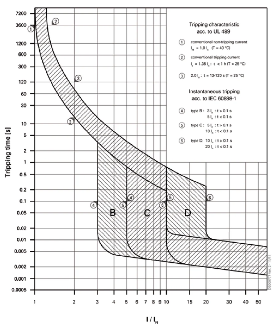 Time-current characteristic curves B, C, and D according to IEC 60898-1
How to Select the Correct Characteristic Curve
The selection is determined not by load power, but by its inrush current. Standard resistive loads—space heaters, incandescent lamps, heating elements—have an inrush current equal to their operating current, making Type B suitable for them.
However, electric motors, transformers, and switched-mode power supplies draw several times their nominal current during initial startup. An electric motor draws 5–7 times its rated current upon starting, while an LED switching driver generates an even higher brief current spike as input capacitors charge. A Type B circuit breaker on such a line would nuisance trip upon every startup, even though no fault exists.
Therefore: B is for lighting, general sockets, and purely resistive loads. C is for mixed residential circuits, main incoming breakers, and the vast majority of standard applications. D is for motors, welding machines, transformers, and large banks of LED drivers.
A crucial caveat: the more "tolerant" the characteristic, the higher the fault current required for instantaneous tripping. For a D16 breaker, this requires 320 amperes despite a nominal rating of only 16 A—and such a high short-circuit current is not achievable on every circuit. We will return to this key engineering point below.
Two Trip Units Inside a Single Enclosure
A circuit breaker operates via two distinct mechanisms, each reacting to different fault conditions.
The thermal trip unit (overcurrent release) consists of a bimetallic strip. As current flows through it, it heats up, deflects, and eventually unlatches the trip mechanism. The higher the overload, the faster the temperature rise. It protects against sustained overcurrent.
Under standard specifications, the thermal trip unit must not trip within one hour at 1.13 times rated current, and must trip within one hour at 1.45 times rated current (for ratings up to 63 amperes, the conventional time is defined as exactly one hour). Thus, during minor overloads, the breaker holds the load for a very long time, which is normal: the cable can also withstand temporary overloads with moderate heating.
The magnetic trip unit (instantaneous release) is a solenoid coil with a spring-loaded core. In the event of a sudden surge in current, the magnetic field mechanically unlatches the mechanism instantaneously, without any thermal delay. It protects against short circuits.
It is precisely the operating range of the electromagnetic release that is designated by the letters B, C, or D.
The Time-Current Characteristic Curve
If you plot a chart where the horizontal axis represents multiples of rated current and the vertical axis represents tripping time, you get a tolerance band rather than a thin line. The standard establishes a corridor within which the device is required to trip, accounting for physical manufacturing variances between individual units.
The left, sloping portion represents the operation of the thermal release, showing an inverse relationship: the higher the overload, the faster the disconnection. For a 16-ampere breaker, the standard allows the following operating intervals:
| Multiple | Current | Tripping Time |
|---|---|---|
| 1.2 × In | 19 A | from 30 minutes upwards |
| 1.5 × In | 24 A | from 3.4 to 46 minutes |
| 2.0 × In | 32 A | from 12 seconds to 6 minutes |
| 2.5 × In | 40 A | from 1.2 seconds to 1 minute |
| 4.0 × In | 64 A | from 0.1 to 2.3 seconds |
The right section represents the instantaneous magnetic zone, which operates more subtly than it appears. Within the characteristic curve's tolerance band (between 5 and 10 times In for Type C), the standard permits either tripping or non-tripping: this is the zone of uncertainty. Guaranteed instantaneous operation is only assured at the upper limit, where disconnection must occur in no more than 0.1 seconds. Real-world devices are usually faster, but engineering calculations must rely strictly on standard normative values.
Between the thermal and magnetic regions lies a transitional section where the primary issue overlooked by amateurs hides.
Short-Circuit Current: The Overlooked Verification
Here is the question that distinguishes a professional engineering approach from a DIY one: will your circuit deliver enough short-circuit current to trigger the instantaneous magnetic release at all?
An old riddle asks: how much current is in a socket? Logically, maximum current = short-circuit current.
During a short circuit, current is limited not by substation capacity, but by the total loop impedance of the entire circuit—from the distribution transformer, through the feeder cable, main breaker, switchboard, and final circuit wiring to the fault point. This impedance is known as the earth fault loop impedance (or line-to-neutral loop impedance).
The calculation is straightforward:
I_sc = U₀ / Z_loop
where Z_loop is the combined impedance of the upstream network up to the switchboard plus the impedance of your circuit conductors in both directions, and U₀ is the nominal phase-to-neutral voltage, 230 volts. Note: 230 V, not 400 V, even if the circuit is three-phase. A fault to the protective earth conductor occurs between phase and earth, meaning phase voltage drives the loop. Substituting line-to-line voltage is a common error that artificially doubles the calculated short-circuit current.
This is where cable length becomes critical. The longer the run and the smaller the cross-sectional area, the higher the loop impedance and the lower the prospective short-circuit current.
An Example Where Everything Breaks Down
Consider a standard socket circuit: 1.5 mm² cable plastered in a wall, a C16 breaker, 16 A design current, and an upstream supply impedance to the board of 0.35 Ω. For guaranteed instantaneous magnetic tripping, a C16 breaker requires 160 amperes.
| Length | Phase-Neutral Loop | Short-Circuit Current | Voltage Drop | What Is Wrong |
|---|---|---|---|---|
| 10 m | 0.640 Ω | 360 A | 1.96 % | All parameters satisfactory |
| 15 m | 0.784 Ω | 293 A | 2.94 % | Voltage drop right at the regulatory limit |
| 20 m | 0.929 Ω | 248 A | 3.92 % | Voltage drop exceeds 3% limit |
| 30 m | 1.219 Ω | 189 A | 5.88 % | Voltage drop is nearly double the allowable limit |
| 40 m | 1.508 Ω | 152 A | 7.84 % | Plus insufficient short-circuit current |
| 50 m | 1.798 Ω | 128 A | 9.80 % | Fails every single compliance check |
Notice that there are two distinct limitations here, and they occur at different lengths. Voltage drop exceeds the 3% limit at just 15 meters. Short-circuit current drops below the magnetic release threshold only at 38 meters. This means the circuit becomes non-compliant long before it loses short-circuit protection.
At 50 meters, the breaker will no longer trip instantaneously during a short circuit—it will fall back into the thermal tripping zone and take seconds to disconnect. During those seconds, a cable carrying 128 amperes instead of its 17.5 A rating will overheat drastically. The breaker is completely functional; it is simply physically unable to perform its protective role on this specific line.
A third subtle detail is immediately noticeable: 1.5 mm² cable plastered inside a wall has a current-carrying capacity of 17.5 amperes, leaving a safety margin of just 8.5% for a C16 breaker. The calculator flags such a pairing in yellow—it formally passes, but standard engineering practice for socket circuits is to step down one rating.
This scenario is extremely relevant for outdoor garden installations where homeowners install external sockets and luminaires, and then plug in a grass trimmer through a 50-meter extension lead.
What to Do When Short-Circuit Current Is Insufficient
There are three solutions, each with its own trade-offs.
- Change the curve to a more sensitive characteristic. If a C16 with a 160 A instantaneous threshold was installed, switching to a B16 ensures tripping at just 80 A. Allowable loop impedance doubles from 1.44 Ω to 2.88 Ω, and maximum line length increases from 38 to 87 meters. This is the least expensive fix, which is why Type B breakers are so commonly recommended for residential buildings. However, it does nothing to solve voltage drop: at 50 meters, voltage drop remains an unacceptable 9.8%.
- Increase cable cross-sectional area. Lower resistance means higher short-circuit current and reduced voltage drop. This is the only method that solves both engineering challenges simultaneously. Upgrading to 2.5 mm² raises short-circuit current to 186 amperes and extends the tripping compliance limit to 61 meters, though this is still insufficient for voltage drop. For a 50-meter line carrying 16 amperes, the calculator indicates a minimum cross-section of 6 mm².
- Reduce line length or relocate the distribution board closer to the load. While not always feasible, this can sometimes be the most economical solution.
There is also a fourth approach: relying on an RCD (Residual Current Device) or an RCBO (Residual Current Breaker with Overcurrent protection). These devices react to earth leakage currents rather than overcurrents, ensuring rapid disconnection during phase-to-earth faults regardless of fault current magnitude. However, during a phase-to-neutral short circuit, an RCD is useless—there is no earth leakage, so overcurrent protection must be provided by the MCB.
Reference Table: Selecting MCB Ratings for Cable Sizes
Values are provided for copper conductors with 70 °C PVC insulation, installed as surface-mounted wiring on a wall (Installation Method C per IEC 60364-5-52), with two loaded conductors at an ambient temperature of 30 °C. The "Marginal" column highlights pairings where the nominal rating formally passes, but leaves a safety margin of less than 10%—in practice, engineers select one step lower for socket circuits.
| Cross-Section | Current Capacity | Maximum MCB Rating | Recommended MCB | Power (230 V) | Typical Application |
|---|---|---|---|---|---|
| 1.5 mm² | 19.5 A | C16 | B16 | 3.7 kW | Lighting, low-power sockets |
| 2.5 mm² | 27 A | C25 (marginal) | C20 | 4.6 kW | General socket circuits |
| 4.0 mm² | 36 A | C32 | C25 | 5.8 kW | Electric cookers, water heaters |
| 6.0 mm² | 46 A | C40 | C40 | 9.2 kW | Apartment main feed |
| 10.0 mm² | 63 A | C63 (marginal) | C50 | 11.5 kW | Main feed, high-power loads |
| 16.0 mm² | 85 A | C63 | C63 | 14.5 kW | Single-family home main feed |
Pay close attention to rows marked "marginal." Pairing a C25 breaker with a 2.5 mm² cable leaves a margin of just two amperes—or seven percent. Formally, standard conditions are met, but at elevated temperatures inside the switchboard or when routed in corrugated conduit, the real current-carrying capacity will be lower than tabular values, completely erasing the margin. A C63 breaker on a 10 mm² cable has zero margin.
Another critical takeaway from the table: these values apply strictly to open surface wiring at 30 °C. That same 1.5 mm² cable embedded in plaster drops to 16.5 amperes, and if two identical circuits run alongside it in the same chase, capacity falls to 11.5 A. Consequently, the maximum breaker rating drops from C16 down to C10. Installing cable "as usual" while taking the MCB rating from an open-wiring table is a widespread and costly mistake.
The minimum cross-sectional area for fixed building wiring is 1.5 mm². A 1.0 mm² conductor is permitted only for flexible appliance leads and internal device wiring.
How to Calculate MCB Rating Based on Power
If your source parameters are in watts rather than amperes, converting them is straightforward.
For single-phase AC networks: I = P / U. A 3.5 kW water heater operating at 230 volts draws 15.2 amperes (3500 W / 230 V = 15.2 A). Thus, it requires a cable no smaller than 2.5 mm² protected by a C16 or C20 breaker.
For three-phase networks: I = P / (√3 × U × cos φ), where U is the line-to-line voltage, typically 400 volts. The power factor (cos φ) is close to 1.0 for resistive loads, and typically 0.8–0,9 for motors.
For lighting circuits utilizing LED drivers, note an important nuance: calculate current using consumed input power, not luminaire optical output power. A driver with 90% efficiency delivering 200 watts of output draws approximately 222 W from the mains. Across ten luminaires, this difference becomes significant.
Additional Factors Affecting Breaker Selection
Breaking Capacity
Beyond nominal current and tripping curve, a circuit breaker has a third critical rating often ignored in residential installations—short-circuit breaking capacity ($I_{cn}$). This is the maximum short-circuit current the device can safely interrupt without destroying itself. It is marked inside a rectangle on the front casing: 4500, 6000, 10000.
The physics is simple. When contacts separate under a short circuit, an electrical arc reaching thousands of degrees forms. The arc chute must extinguish this arc. If fault current exceeds the rated breaking capacity, the chute fails, causing the breaker to melt and explode, leaving the circuit closed.
For an apartment in a high-rise building, 4500 A is generally sufficient; however, the closer an installation is to the distribution transformer, the higher the short-circuit current—main switchboards and private homes near substations require 6000 A or 10000 A devices. Note that for three-pole breakers, three-phase short-circuit current governs rather than single-phase current, yielding roughly double the fault current. This parameter depends on supply network conditions rather than internal wiring; while obtainable from utility providers in an ideal world, the practical rule of thumb is: the higher the breaking capacity, the better.
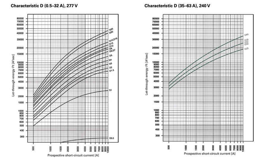 Marking of rated short-circuit breaking capacity in amperes
Switchboard Ambient Temperature
Circuit breakers are calibrated at an ambient temperature of approximately 30 °C. Inside a tightly packed switchboard—especially next to high-load devices—temperatures can reach 45–50 °C, causing the thermal trip unit to operate below its nominal current rating because the bimetal is already preheated.
Practical consequence: in a cramped distribution board, a breaker may trip under currents formally within its normal range. Manufacturers provide temperature derating coefficients, but practically it is usually sufficient to leave ventilation spacing between devices and avoid packing boards to full density.
Protection Discrimination (Selectivity)
When circuit breakers are installed in series—main incoming, group distribution, and sometimes a final appliance breaker—it is vital that a fault trips only the device immediately upstream of the fault, rather than shutting down the entire switchboard.
Achieving total selectivity under short-circuit conditions is challenging: both breakers experience the same fault current and both trip within milliseconds. However, overcurrent selectivity works effectively if nominal ratings are separated by at least two steps. Therefore, with 16 A final circuit breakers, it is wise to select a 32 A or 40 A main breaker rather than a 20 A one.
Common Mistakes
- Oversizing the breaker "just in case." This is the most common and dangerous error. Safety margins belong to the cable, not the breaker. An oversized breaker simply will not protect the line.
- Selecting based on load while ignoring the cable. Appliances change, but wiring inside walls remains. Always calculate based on conductor cross-section.
- Installing Type D everywhere nuisance tripping occurs. If a breaker trips during motor startup, the curve is indeed wrong. But if it trips during steady-state operation, it is an overload—replacing it with Type D effectively disables overcurrent protection.
- Failing to verify short-circuit current. As demonstrated above, on long runs a breaker may be physically unable to trip instantaneously.
- Ignoring voltage drop. As shown in our example, on extended runs voltage drop hits regulatory limits before any other parameter, and most frequently governs required conductor size.
- Using open-air cable tables regardless of installation method. In conduits, chases with bundled circuits, or warm rooms, allowable current-carrying capacity drops by a third or more.
- Assuming an RCD replaces a circuit breaker. These are completely different devices for different tasks. An RCD detects earth fault leakage; an MCB protects against overcurrents and short circuits. An RCBO combines both functions, but neither eliminates the need for overcurrent protection.
- Ignoring selectivity. If an incoming breaker and a downstream group breaker have close nominal ratings, a fault in a single circuit can trip the entire switchboard. Upstream breakers should generally be at least two rating steps higher than downstream ones.
How to Use the Calculator
The widget above models the behavior of protective devices on a specific circuit and runs seven professional engineering compliance checks—the exact same ones performed by electrical designers.
Two Operating Modes
The yellow toggle at the top selects calculation depth. In Basic mode, there are ten input parameters: circuit type, nominal current rating, curve characteristic, voltage, conductor cross-section, line length, installation conditions, earthing system, RCD presence, and loop impedance. This is sufficient to obtain an accurate answer.
In Expert mode, eleven additional parameters unlock: IEC installation method classification, ambient air temperature, number of bundled circuits, number of loaded conductors, thermal insulation presence, protection device type (MCB or gG fuse link), voltage drop limit, power factor, breaking capacity, protective earth cross-sectional area, and required disconnection time. Everything automatically defaulted in Basic mode can be overridden here.
Loop Impedance: Calculated vs. Measured
This is a critical engineering distinction worth mastering. Loop impedance can be specified in two ways.
Calculated. You input the supply network impedance upstream of the switchboard, and the calculator automatically adds the cable impedance based on cross-section and length, assuming conductors at an operating temperature of 70 °C. This is used during the design stage before wiring is installed. The resulting value is compared directly against the U₀/Ia threshold.
Measured. You input a reading taken with a meter directly at the load terminals. Cable impedance is already included in this reading and is not added a second time. Here, a different threshold applies—two-thirds of U₀/Ia—because measurements are taken on cold conductors, whereas standards apply to hot conductors. The difference is significant: for a B16 breaker, the calculated threshold is 2.875 Ω, while the measured threshold is 1.92 Ω.
Values are entered as decimals accurate to three decimal places, allowing direct entry of instrument readings such as 0.23 Ω. Presets ("city," "rural," "far from substation") remain available for cases where an instrument is unavailable.
The Current Slider and Color-Coded Zones
The bar beneath the slider is divided into color-coded zones, each representing a specific circuit operating state.
- Green — normal operation: the breaker holds the load and the cable is within allowable thermal limits.
- Blue — the cable is overloaded, but the breaker does not detect it yet. This zone appears only when the breaker rating is incorrectly selected, and shrinks to zero under proper coordination. Moving the slider through this zone visually demonstrates why the coordination rule is essential.
- Yellow — the thermal trip unit is active; tripping time is measured in seconds, minutes, or hours.
- Orange — the zone of uncertainty between the lower and upper limits of instantaneous magnetic tripping. The solenoid may or may not trip: the standard permits both behaviors.
- Red — above the upper instantaneous limit; instantaneous tripping is guaranteed.
The Graph
On the right is the time-current characteristic curve plotted from standard regulatory test points. The solid colored band transitioning from yellow to red represents the tolerance corridor within which the device must operate: from the thermal overload region, through the zone of uncertainty, to guaranteed instantaneous tripping.
The green area on the left represents normal operation. It terminates at either 1.13 times In, or earlier if the cable's current-carrying capacity is lower.
The blue dashed curve represents the thermal limit of the cable itself. This is perhaps the most useful visual element: if it runs above the breaker characteristic curve, the cable is protected; if it intersects the curve, then at certain fault currents the cable will burn before the breaker trips. Try selecting a 1.5 mm² cable with a D25 breaker—you will see an intersection. Switch to 4 mm², and the curve moves safely upward. A bright dashed line highlights the region up to 5 seconds where the adiabatic thermal stress equation is valid, while a faded dashed line shows where it is not.
The point with a vertical line segment shows your current operating coordinate and the tripping time interval. A triangle on the axis marks design current even when the breaker holds the load and no coordinate point exists on the curve.
Seven Verification Checks
Below the result is a checklist with green, yellow, and red status markers. Each row displays the regulatory formula alongside substituted numerical values, showing not only whether a test fails, but by how much.
- Rule 1, Overload Protection:
Ib ≤ In ≤ Iz. - Rule 2, Tripping Factor:
I₂ ≤ 1.45 · Iz. Automatically satisfied for MCBs, but becomes the governing constraint for gG fuses. - Disconnection Time:
Zs ≤ U₀/Iafor TN systems;RA × IΔn ≤ 50 Vfor TT systems. - Voltage Drop: verified against the selected percentage limit.
- Cable Short-Circuit Thermal Withstand:
I²t ≤ k²S², checked independently for phase and protective conductors. - Breaking Capacity: prospective short-circuit current at the switchboard compared against device rated short-circuit breaking capacity.
- RCD Requirement: mandatory 30 mA residual current protection for general socket and residential lighting circuits.
Summary Footer
The bottom block compiles all parameters into a single concise string such as: C25 · Cu/PVC 4 mm² · B2 · 20 m · 230 V · TN · RCD 30 mA · Iz 31.8 A · Zs 0.571 Ω · ΔU 1.75 %, followed by over thirty detailed rows grouped by circuit, device, cable, environment with correction factors, mains supply, and results. You can also inspect the exact calculation of allowable current: for example, 23 × 1.06 × 0.70.
The "Copy" button places this complete summary into your clipboard as plain text—ideal for pasting into technical reports or engineering correspondence. Valuable metrics absent from ordinary calculators include: maximum line length by voltage drop, maximum line length by disconnection time, and the minimum conductor cross-section that satisfies all seven compliance checks simultaneously.
Engineering Basis of Calculations
The calculator above is not based on empirical guesswork. Every single value is extracted from specific tables within recognized international standards, as detailed below. This is deliberate: an engineer can debate a number backed by a standard citation, but cannot debate an arbitrary figure.
Allowable Current-Carrying Capacity
Calculated as Iz = Iz,table × k₁ × k₂ × k₃, where base values depend on installation method and correction factors account for environmental conditions.
| Parameter | Standard | Table or Clause |
|---|---|---|
| Base Current-Carrying Capacity | IEC 60364-5-52 = HD 60364-5-52 = DIN VDE 0100-520 | Table B.52.4: copper, 70 °C PVC, Installation Methods A1, A2, B1, B2, C, E, two and three loaded conductors, 30 °C |
| Ambient Temperature Correction k₁ | IEC 60364-5-52 = HD 60364-5-52 = DIN VDE 0100-520 | Table B.52.14 |
| Grouping Correction k₂ | IEC 60364-5-52 = HD 60364-5-52 = DIN VDE 0100-520 | Table B.52.17: "bunched in air, in conduit, in wall" row for methods A1, A2, B1, B2; "single layer" row for method C |
| Thermal Insulation Correction k₃ | IEC 60364-5-52 = HD 60364-5-52 = DIN VDE 0100-520 | Clause 52.6 |
| German equivalent of the same tables | DIN VDE 0298-4 | current-carrying capacity tables |
Overload Protection
| Condition | Standard | Explanation |
|---|---|---|
Ib ≤ In ≤ Iz and I₂ ≤ 1.45 · Iz | IEC 60364-4-43 / DIN VDE 0100-430 | Clause 433, two conditions rather than one |
I₂ = 1.45 · In for MCBs | EN 60898-1 / DIN VDE 0641-11 | therefore the second condition is automatically satisfied |
I₂ = 1.6 · In for gG fuses | IEC 60269-1 / DIN VDE 0636-10 | 1.5 and 1.9·In up to 16 A, 1.25 and 1.6·In above; the second condition becomes governing |
Characteristic Curve Reference Points
Curves are plotted using standard test verification points rather than estimated visual shapes.
| Point | EN 60898-1 Requirement |
|---|---|
| 1.13 · In | does not trip within conventional time (1 hr for ratings ≤ 63 A) |
| 1.45 · In | trips within conventional time |
| 2.55 · In | between 1 and 60 s for ratings ≤ 32 A, between 1 and 120 s above |
| lower instantaneous limit | does not trip within 0.1 s — 3·In for B, 5·In for C, 10·In for D |
| upper instantaneous limit | trips within 0.1 s — 5·In for B, 10·In for C, 20·In for D |
Between these points, the standard does not specify curve geometry, so mathematical interpolation is used. This does not affect compliance outcomes: all verifications rely directly on regulatory reference points rather than interpolated values between them.
Automatic Disconnection of Supply (ADS) Under Fault Conditions
| Parameter | Standard | Table or Clause |
|---|---|---|
Condition Zs · Ia ≤ U₀ | IEC 60364-4-41 / DIN VDE 0100-410 | Clause 411.4, TN system |
| Required Disconnection Time | same | Table 41.1: 0.4 s for final circuits up to 63 A at 230 V, 5 s for distribution circuits |
| Disconnection Current Ia | DIN VDE 0100-600 | Table NA.1: for B, C, D MCBs at 0.4 s; for gG fuses at 5 s |
| Measured Value Correction Factor | DIN VDE 0100-600 cl. C.61.3.6.2, DIN EN 60204-1 cl. A.4.3 | Zs,meas ≤ 2/3 · U₀/Ia — accounts for conductor heating during short circuit |
| TT System Condition | IEC 60364-4-41 | RA × IΔn ≤ 50 V; disconnection is provided by RCD, not MCB |
| Mandatory 30 mA RCD Requirement | DIN VDE 0100-410:2018-10 | socket circuits up to 32 A, lighting circuits in residential premises |
Conductor Properties, Short-Circuit Current, and Voltage Drop
| Parameter | Standard | Value or Clause |
|---|---|---|
| Conductor Resistance | IEC 60228 | Class 2, maximum allowable values at 20 °C tabulated independently for each cross-section |
| Conductor Temperature for Loop | — | 70 °C, temperature coefficient 0.00393 K⁻¹ |
| Maximum Short-Circuit Current | IEC 60909 | voltage factor Cmax = 1.05 |
| Cable Thermal Short-Circuit Withstand | IEC 60364-4-43 | S² ≥ I²t / k², k = 115 for copper with PVC; equation valid up to 5 s |
| Protective Conductor Cross-Section | IEC 60364-5-54 | Table 54.2; verified independently if PE is reduced |
| Breaking Capacity | EN 60898-1 | Icn 6000 and 10000 A |
| Voltage Drop Limit | DIN 18015-1 / DIN VDE 0100-520 / HD 60364-5-52 | 3% from meter, 4% from building entry (Clause 525), 3% and 5% per Annex G |
Two Notes on Regulatory Conventions
Allowable loop impedance is calculated as U₀/Ia, without the Cmin voltage factor. This follows German practice under DIN VDE 0100-410, upon which Table NA.1 is constructed. British standard BS 7671 applies Cmin = 0.95 and uses a 0.8 correction factor for measured values instead of 2/3. This yields different thresholds, and the two traditions must not be mixed: for a B16 breaker, the German approach gives 2.875 Ω calculated and 1.92 Ω measured, whereas the British approach gives 2.73 Ω and 2.18 Ω. The British measured limit is 14% more lenient.
Conductor resistance is taken from IEC 60228, rather than using the simplified constant γ = 56. Real stranded conductors have slightly higher resistance than solid copper: for 2.5 mm², the difference is about 3.6%, always tending toward an underestimation of loop impedance. On short lines this is imperceptible, but on long lines it becomes decisive.
What the Calculator Does Not Cover
Explicit scope boundaries are just as important as formulas. Not covered: aluminum conductors and 90 °C XLPE insulation, underground installations, main and distribution feeders, harmonic currents and neutral heating, selectivity with upstream devices, Arc Fault Detection Devices (AFDD), diversity/coincidence factors, and explosive atmospheres.
Applicable scope — final AC circuits in TN and TT systems: copper, 70 °C PVC, nominal ratings up to 63 A, cross-sections up to 35 mm², installed in free air, in walls, or in conduits.
Key Takeaways
- The circuit breaker protects the cable, not the load. The correct engineering order: first, select the cable for the load; then, select the breaker for the cable.
- The coordination rule:
operating current ≤ breaker rating ≤ allowable cable current. Violating the upper limit means the circuit is unprotected against overloads. - Tripping characteristics are selected based on inrush current, not power. Type B is for lighting and sockets, Type C is universal, and Type D is for motors and transformers.
- On extended lines with small cross-sections, short-circuit current can drop below the magnetic release threshold. When this occurs, the breaker defaults to its thermal zone, allowing the cable to overheat—verifying loop impedance is mandatory.
- Voltage drop reaches regulatory limits before short-circuit current does. In our worked example, this occurred at 15 meters versus 38 meters. Voltage drop is most frequently the governing factor for required cross-sectional area.
- Tabular current ratings assume open-air installation at 30 °C. Inside conduits, wall chases with bundled cables, or warm enclosures, allowable current-carrying capacity drops by a third or more—and the maximum permissible MCB rating drops with it.
Finally: any formulaic calculation remains an engineering estimate. Actual earth fault loop impedance must be verified using a dedicated instrument (a Loop Impedance Tester), and electrical system design should be performed by a qualified electrical specialist. If you own a tester, switch the calculator to "Measured" mode and enter your instrument reading—compliance will then be evaluated against measured-value regulatory standards. In electrical installations, the cost of an error is not always measured purely in money.
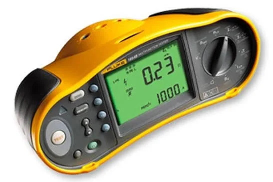 Professional Earth Fault Loop Impedance Tester