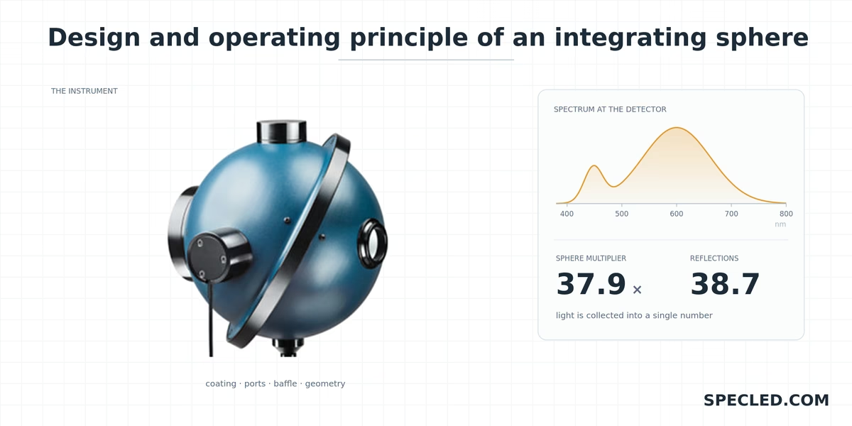
Accurate measurement of all light source characteristics is a complex engineering task. If you need to know the illuminance of a desk's working surface, simply placing a portable lux meter on it is enough. But how do you measure all the light emitted by a light source in every direction? How do you accurately determine the total luminous flux in lumens or the total number of photons (PPF, in µmol/s)?
To solve this problem in optics, an Ulbricht sphere — or integrating sphere — is used. This article presents our interactive simulator, which allows you to look inside a rather rare and expensive device, explore the physics of measurements, compare the quality of the sphere's wall coatings, and visually see how the final result is formed on the detector.
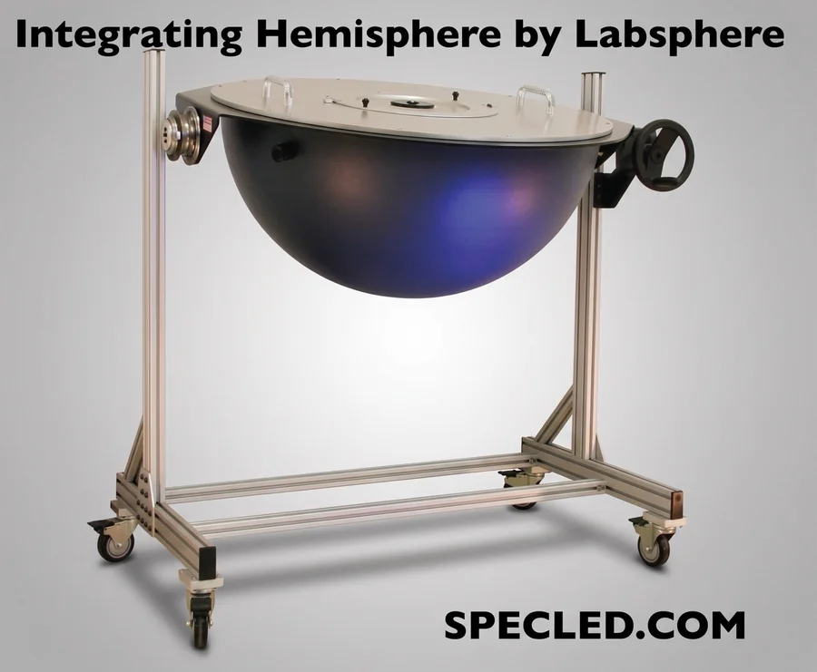
An integrating sphere (Ulbricht sphere) is a precise instrument used for collecting, scattering, and accurately measuring optical radiation (light) from various sources. The sphere performs the task of spatial integration of the luminous flux. Depending on the tasks at hand, there are spheres ranging from 5 cm to several meters in diameter, inside which bulky test samples, such as powerful LED lamps, can be placed.
For reference:
In 1892, English physicist William Edward Sumpner published a fundamental scientific work. In it, he mathematically described how luminous flux behaves inside a hollow sphere with perfectly scattering (diffuse) white walls.
In 1900, German engineer and professor of electrical engineering Richard Ulbricht built the world's first working integrating sphere. He published the results of his experiments in 1900.
Any light source (whether an LED, incandescent lamp, or candle) emits light unevenly. In one direction, the rays are powerful, while in another, they scatter or are blocked by the lamp's own housing.
The sphere solves this problem through its geometry and perfect scattering (spherical shape). Light entering inside undergoes multiple diffuse reflections from the internal walls. As a result, the illuminance of any point on the sphere's inner surface becomes strictly proportional to the total luminous flux of the source, regardless of the direction the rays initially flew. This is spatial integration.
Accurate knowledge of the total lumen flux, photon flux (PPF), and spectrum is the foundation for creating high-quality lighting, including grow lights for plants. Manufacturers need to understand how many photons an LED or a designed ready-made lamp delivers under ideal conditions. For testing, manufacturers use rigs that include integrating spheres.
When you need to verify the effectiveness of an already purchased LED fixture in practice, an integrating sphere is not used. Many enthusiasts or growers have a household lux meter in their arsenal, which can even be built into a smartphone. To test LED plant grow lights, we created a highly accurate lux to PPFD calculator↗, allowing you to select a spectrum from available presets or set it manually. Our calculator accurately converts the illuminance level in lux into the lighting level for plants — PPFD.
How does an integrating sphere work: principle and design
Let's break down how an integrating sphere works and how it is designed, based on our interactive educational widget. The design of the sphere seems simple but conceals numerous physical nuances to achieve stunning measurement accuracy.
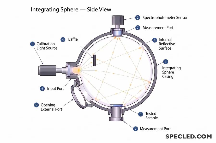
- The body of the integrating sphere usually has external ports for connecting sensors, light sources, or test samples, as well as a reference light source for calibration.
- A spectrophotometer sensor is connected to one of the external ports, and the light is transmitted via an optical cable directly to the spectrophotometer sensor.
- A calibration light source is needed to introduce compensating coefficients into the measurements for losses that inevitably occur due to the design features of the sphere and the measured light source, especially if the source is placed inside the sphere.
- A baffle built into the sphere casts a shadow on the spectrophotometer sensor, as direct rays falling straight onto the sensor without spherical integration will inevitably lead to greatly inflated readings.
- A measurement port is used when it is necessary to accurately measure the transmittance of the test sample or its reflectance.
- A port where the reference light source is installed. Usually, this is a halogen lamp, the physical parameters of which are previously measured with enormous accuracy. The cost of such lamps can reach $1000 per unit. Power is supplied through a highly precise and stabilized power supply. The working lifespan of calibration light sources is typically 50 hours, after which the lamp's parameters deviate from their original values.
- A port for connecting the spectrophotometer sensor. It is shaded by an internal baffle to prevent direct light rays from the test sample falling on it.
- An internal reflective surface made of a special material called Spectralon. This is a special material with a 99% reflectance.
Integrating sphere working principle and internal coating
An integrating sphere, the working principle of which is based on Lambert's law, requires an absolutely matte (diffuse) wall coating with the highest reflectance (about 99%). Specular surfaces are detrimental to the sphere. This is why Spectralon was developed by Labsphere, considered the whitest substance on Earth with a reflectance of 99% in the 250-2500 nm range. It is chemically and thermally stable and can be washed.
In the simulator, you can switch coating types:
- Barium sulphate: A classic and inexpensive coating. Reflects about 96-97% of light.
- Spectralon: A reference fluoropolymer material with a reflectance of over 99% over a broad wavelength range.
- White paint: A budget option with 90% reflectance, highly absorbing the blue spectrum. Spectrum reflection in the visible light range is non-linear.
Barium sulphate (BaSO₄) is an inorganic substance that is insoluble in water and completely non-toxic. Found in nature as the mineral barite. Barium sulphate has a reflectance of about 96-98% but in a narrower 400-1200 nm range.
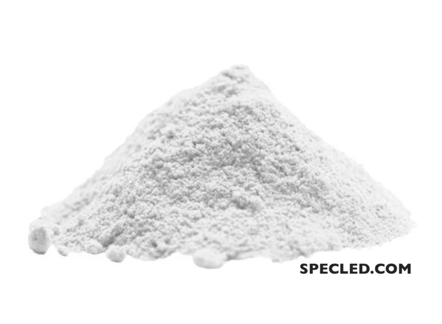
Barium sulphate powder, even purified laboratory grade, is cheap — about $10 per 100 grams. This is incomparable to the price of Spectralon. Therefore, barium sulphate powder is often used to coat the inner surface of semi-industrial or homemade integrating spheres, which are self-produced and perfectly suitable for various measurements, especially those that do not require ultra-high precision.
White paint is the cheapest coating, available in any hardware store. It is suitable only for demonstrating the sphere's operation to students or for basic measurements by DIY enthusiasts.
A perfectly white integrating sphere coating allows for accurate spectral data collection for different areas, such as plant lighting or household lamp design. A spectrometer connected to the sphere measures not only the quantity but also the quality of white light. You can learn more about why light quality is important for eye health and what colorimetry is in our article about the CRI, CQS color rendering index and the TM-30 standard↗.
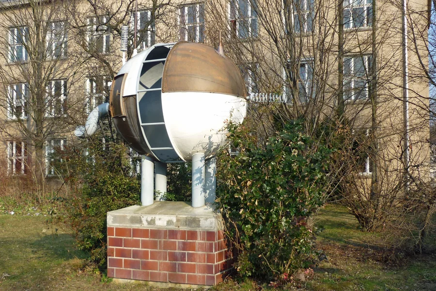
Interesting fact: the first integrating sphere built by Richard Ulbricht was coated inside with calcium carbonate. It sounds intimidating to those unfamiliar with chemistry, but it is just ordinary chalk. At the Dresden University of Technology, where the inventor worked, there is even a monument erected in his honor in the shape of an integrating sphere.
Spectrum Distortion at the Detector
In an ideal world, the coating reflects all wavelengths equally. In reality, barium sulphate slightly absorbs blue light. Look at the spectrum graph in the widget: the dotted line (Measured) can differ from the solid one (True). The higher the sphere multiplier (the more internal reflections), the more the absorption error accumulates. In the widget, the Blue 400-500 measured / true metric visually demonstrates how many blue photons the sphere "ate" compared to the actual source.
Open ports also affect the result: they are "black holes" through which light escapes irretrievably. The larger the port area relative to the sphere area, the lower the multiplier and the worse the integration.
Baffle in an Integrating Sphere
A baffle is a small plate coated with the same reflective substance as the entire inner surface of the sphere, designed to create conditions for multiple, diffuse reflection of light from the perfectly white inner coating of the sphere, making the light uniform before measurement by the spectrophotometer.
The light detector (spectrometer or photodiode) is mounted in the sphere's wall. If rays from the lamp hit it directly, without reflections, the readings will be critically distorted. Therefore, a baffle is always installed in front of the detector. Try switching the baffle in the widget to the Removed mode, and you will see how a direct ray (First bounce in the signal) hits right into the sensor, breaking all the calculation math.
Functions performed by the baffle:
- Exclusion of direct illumination — shades the external port of the integrating sphere to which the spectrophotometer sensor is connected, preventing direct (non-integrated) rays from the light source from illuminating the sensor. Direct rays heavily distort data.
- Protection from the first light reflection — the sensor must not see the direct light spot from the light source. It is this function of the baffle that ensures the measurement's independence from the light source's radiation pattern.
For some measurements, there may be several baffles in the sphere; however, the more elements inside the sphere, the worse, as any heat inside the sphere only adds to the error.
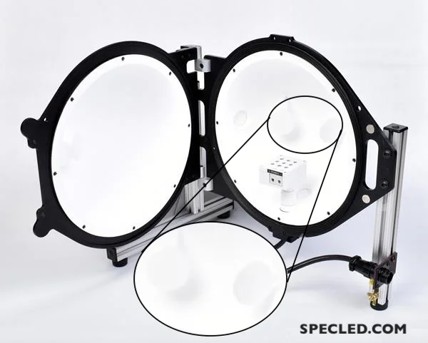
External ports and what is an integrating sphere used for
An integrating sphere can perform tasks beyond just measuring the total luminous flux of a light source. The sphere allows measuring the total reflectance of a test sample, diffuse reflectance, total transmittance (transparency), and diffuse transmittance.
For example, when creating secondary optics for LEDs, one of the main parameters is the optics' efficiency or its transmittance. It is this parameter that can be measured with an accuracy of fractions of a percent in an integrating sphere using a special port configuration.
Summary Table of Port Configurations
| Measurement Method | Where the sample is located | What is done with the additional (opposite) port? |
|---|---|---|
| Total Reflectance | On the reflection port | The specular trap port is closed with a reflective plug. |
| Diffuse only (Reflectance) | On the reflection port | The specular trap port is open (light escapes into the void). |
| Total Transmittance | On the input port | The opposite port is closed with a reflective plug. |
| Diffuse only (Transmittance) | On the input port | The opposite port is open to let direct radiation out. |
The external port also allows a Light Trap to be physically connected to the sphere. Such a trap solves one of the most important tasks in optical measurements: separating light into diffuse (scattered) and specular (glossy glare) components.
Why is this needed:
1. When measuring reflectance (SPIN and SPEX modes)
When a light beam hits a sample at a small angle (e.g., 8 degrees), light reflects in two ways:
- Specularly (like from a mirror): reflects strictly at the same angle (8 degrees) in the opposite direction. This is a glossy glare.
- Diffusely: scatters in all directions inside the sphere due to the material's texture.
Port CLOSED with a white plug (SPIN mode — Specular Component Included): The specular glare hits the plug, scatters inside the sphere, and is registered by the detector along with all the rest of the light. You are measuring the total reflectance (true color + gloss).
Port OPEN to the outside or a LIGHT TRAP is installed (SPEX mode — Specular Component Excluded): The specular glare flies through this port, enters a "black dead-end" (trap), and is completely absorbed there. This is a measurement of purely diffuse reflectance.
Why does this matter in practice? To understand how glossy or matte an object is. If you subtract the SPEX results from the SPIN results, the instrument will output the pure specular gloss coefficient. This is critical in the production of car paints, plastics, or printing, where the color is the same, but the clear coat finish is different.
2. When measuring transmittance
- The test sample is placed on the input port, and a light beam is passed through it. If the additional port is CLOSED with a white plug, total light transmittance is measured. Port closed — means all light stays in the sphere. For example, 1000 lumens enter from a known light source, and the spectrophotometer records 970 lumens. Thus, the transparency coefficient for the test object is 97%.
- A light beam is passed through the test sample, but the additional port is OPEN or a TRAP is installed. Two opposite ports are used for measurement; light passes through the test sample and goes outside or is extinguished in the trap. Only the light that the sample scattered remains in the sphere. This is how Haze or the diffuse transmittance coefficient is measured.
Light Trap and its Application
Using a light trap instead of a port open to the outside of the integrating sphere:
- If you simply open the port to the outside, there is a risk that the lights in the lab are on or the room walls reflect something — this external radiation will "climb" back into the sphere through the hole and distort the detector readings.
- A Light Trap is an absolutely isolated geometric trap (usually painted a deep matte black inside or consisting of inclined mirrors). Light entering it is reflected multiple times from the black walls and fades by 99.9%, guaranteeing a perfect zero ("absolute darkness") for this beam.
Sometimes a light trap is called a black "dead-end". It is also used for Zero Calibration of the spectrophotometer.
IMPORTANT! When using an integrating sphere, all unused ports must be closed with special reflective plugs!
Luminous Flux Measurement: 2π and 4π Geometries
When measuring the total luminous flux (lumens) of light sources (lamps, LEDs, fixtures) in an integrating sphere, two fundamentally different measurement schemes are used: 4π geometry (spherical) and 2π geometry (hemispherical).
The essence of these terms is taken from geometry: the full solid angle around a point (the entire sphere) is equal to 4π steradians, and half of a sphere (hemisphere) is 2π steradians.
2π Geometry (Source at the port)
Used for directional light sources: bare LEDs, COB arrays, spotlights, and modules. The source is mounted outside, flush with the edge of the measurement port, and shines into the sphere (into the front hemisphere, 2π). In this case, the bulky fixture housing is not placed inside the sphere, and the returning light is absorbed only by the front panel of the LED, drastically reducing self-absorption errors.
By the way, reflection efficiency is important not only in the laboratory. In home grow tents, walls made of Mylar Diamond or white matte paint work on a similar principle, forcing some of the rays to effectively return to the plant leaves. A grow tent lighting simulator↗ will help you calculate the efficiency and uniformity of lighting.
As is clear from the image, the 2π measurement method will not allow measuring the parameters of an HPS lamp or a regular incandescent lamp. For light sources that emit almost 360 degrees around themselves, you must only use the 4π measurement method and a fully-fledged integrating sphere.
4π Geometry (Source inside)
In this mode, the lamp is suspended right in the center of the sphere on a special rod. Light is emitted in all directions (solid angle 4π steradians). This is the standard for measuring incandescent lamps, grow lights, HPS, CFLs, and some A60 LED lamps. The main problem with this geometry is Self-absorption. Light, bouncing multiple times inside the sphere, inevitably hits the lamp housing itself or the fittings and gets absorbed. In the widget, this parameter is presented on a separate line and measured in %.
The Self-absorption problem is solved by calibrating the integrating sphere using a reference light source, which I will write about below.
What is the Main Difference? (Direct Comparison)
| Characteristic | 4π Geometry | 2π Geometry |
|---|---|---|
| Source Position | Inside the sphere (in the center) | Outside the sphere (on the port) |
| Radiation Direction | In all directions (360°) | Forward only (into the hemisphere) |
| Self-absorption Impact | High. The lamp housing and wires absorb part of the reflected light. An Auxiliary Lamp is required for compensation. | Minimal. The fixture housing is outside and does not absorb light reflected by the sphere. |
| Size Limitation | The source must be small (usually recommended no more than 10% of the sphere's volume). | The source can be large, as long as the light beam fits through the port. |
| Calibration | More difficult, since the reference lamp must also hang in the center. | Simpler and faster. |
The problem with the geometric dimensions of the test light sources is also partially solved by calibration. Especially in situations where a large light source with a black housing, such as a concert LED spotlight, is placed in the sphere.
When additional calibration is used, the area of the test object can reach up to 20-30% of the integrating sphere area. However, large objects introduce distortions into the geometric parameters of the entire rig, which leads to an increase in measurement error.
Sphere Multiplier
The integrating sphere multiplier (denoted by the letter M) is a key dimensionless parameter in optics that shows how many times the luminous energy density (illuminance) inside the sphere increases due to multiple internal reflections compared to if the light had simply fallen once on a flat white diffuser of the same area.
From a practical point of view, the multiplication factor has two clear physical meanings:
- Average number of reflections — a related but different number. A photon hits the wall on average 1/(1 − ρ(1 − f)) times before it is absorbed by the coating or escapes through a port. The multiplier is that figure multiplied by ρ, so on a good coating the two are almost identical and on a poor one they visibly diverge. The widget shows both side by side: with Spectralon you get about 31 and 31, with ordinary white paint 6.9 and 7.8.
- Signal gain coefficient: The sphere acts as an optical "amplifier" for the sensor. Due to multiple reflections, the illuminance at the detector turns out to be an order of magnitude higher than with a direct measurement, which is critically important for measuring weak light sources.
What should the multiplier be in a good sphere?
For high-quality laboratory integrating spheres, a value of M in the range of 10 to 30 (rarely up to 50) is considered normal.
- If M is too small (less than 10): The sphere mixes light poorly. The radiation makes few internal reflections, and uneven beams of light can hit the detector, causing a severe error.
- If M is too large (more than 50): The sphere becomes hypersensitive to any changes. The moment you bring a tiny sample (even within 10% of the size) inside, overall absorption spikes sharply, the multiplier collapses, and the system throws a massive error that is difficult to correct even with an auxiliary lamp.
Therefore, engineers are always looking for a balance: they make the inner coating as reflective as possible, and limit the port area and sample size to keep the sphere multiplier in a stable operating range.
Interactive Simulator - Explaining Theory and Practice
Now, after getting acquainted with the general theory, principle of operation, and the purpose of using integrating spheres, I suggest looking at our interactive widget simulator designed to educate and visually demonstrate how integrating spheres work.
The metrics at the bottom of the widget will help you understand exactly what parameters can be measured using an integrating sphere. You can compare the difference in the sphere wall coating material, visually see the integrating sphere calibration steps, how an open, unplugged port affects measurements, and how the sphere multiplier changes depending on its diameter.
Integrating sphere calibration procedure
Since the sphere distorts the spectrum, loses some light through the ports (even when closed), and the self-absorption of the test source (if it is inside) affects measurements, the spectrophotometer will not give the correct result immediately after connection. An exact calibration is almost always a mandatory process before any measurements.
How to calibrate an integrating sphere
To understand the process better, here is a detailed breakdown. The calibration procedure consists of three mandatory steps:
Integrating sphere step by step calibration
- Using a Standard Reference Lamp: A special halogen lamp, certified by a national metrology institute (e.g., NIST), is placed in the sphere. Its exact luminous flux and spectrum are known down to the thousandth fractions. The spectrometer takes readings, the software compares them with the reference datasheet, and creates a base spectral correction file.
- Auxiliary Lamp Compensation: An auxiliary lamp is built into the sphere's wall. First, it is turned on with an empty sphere (Spectrum A is recorded). Then, the bulky test fixture is placed in the powered-off sphere. The auxiliary lamp is turned on again (Spectrum B is recorded). The difference between A and B is the exact amount of light the test fixture "eats" with its dark housing.
- Conducting Measurements: The test fixture is turned on. The spectrometer software, using the base calibration file from Step 1 and the self-absorption coefficient from Step 2, calculates the True Spectrum and the exact luminous flux of the source.
- Obtaining final data on the object under study and analyzing them.
Sphere calibration allows measuring the parameters of virtually any light source or taking parameters of various optics with stunning accuracy. This is why the integrating sphere is an indispensable tool for a large number of different researches.
Conclusion
The integrating sphere is a fundamental optical instrument without which the existence of the modern lighting industry is impossible. Despite the apparent simplicity of the "white ball," complex physical processes of light integration occur inside it. Use our interactive simulator to better understand the impact of materials, geometry, and internal baffles on the final result of photometric measurements.
The SPECLED brand specializes in the professional development and assembly of LED grow lights for plants. To achieve maximum quality and efficiency in our products, we use a professional Ocean Optics STS-VIS spectrophotometer for measurement and research purposes.
We also create interactive calculators and educational widgets for clear, interactive learning and explaining the sometimes complex physical principles related to electronics or LED lighting. An example is the widget located at the top of this page, which visually demonstrates the physical working principle of an integrating sphere.
However, we decided not to stop at just interactive widgets and useful calculators! Specifically for DIY enthusiasts in LED-related fields—such as grow lights, LED flashlights, domestic lighting, or industrial lighting—we have created a professional tool for digitizing LED spectrums↗ and further spectral analysis.
Our tool allows you to digitize an LED spectrum directly from a datasheet, where documentation often displays the spectrums of LEDs with different color temperatures on a single graph. Now you can digitize each spectrum individually, get spectral distribution data, evaluate the amount of light in the 650-670 nm range (crucial for plants), and obtain calculated data like the CQS and TM-30 color rendering indices—for instance, when you only have the spectrum but lack other data.