Why Don't All LEDs Light Up When Connected in Parallel?
Building a "chandelier" out of a bunch of different LEDs and powering them from a single powerful driver sounds like a great plan to save money and time. It's just a pity that this plan usually doesn't work, and you end up having to carefully choose an LED driver, sometimes even using two drivers simultaneously.
The worst-case scenario looks like this:
1. We assemble LED circuits on a heatsink;
2. Connect the assembled structure to the driver;
3. Plug the driver into the mains;
4. A flash, and half of the LEDs go into the trash. It sure was bright, though...
How to Wire LEDs in Parallel: Learning It on the Simulator
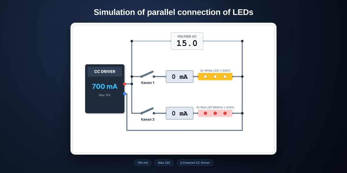
The widget above is a textbook parallel LED circuit. A constant-current driver rated at 1400 mA — exactly what two 700 mA strings need. That is precisely the reasoning behind most attempts to save the cost of a second driver. Two channels hang off it: three white 5000 K emitters on the first, three red 660 nm on the second.
Start with the switches. Close them one at a time and each string behaves perfectly. Close both — build a real parallel circuit — and it falls apart: the bus collapses to 6.4 V, the white ammeter reads zero, and the red string takes all 1400 mA. That is 200 % of its rating. Within half a minute the junction passes 115 °C against a 110 °C limit, and the widget turns the verdict red.
Notice what happens with the second switch still open. Leave only the white channel closed and it also takes the full 1400 mA, heating to 156 °C. This is not a contrived case: it is exactly how the circuit behaves when one of the two strings fails open. The survivor instantly inherits double the current.
Then the useful part begins. The simulator is not a single scripted scenario — you can build any pairing in it.
Driver current selector. Tap the figure on the driver itself or pick from the list: 350, 700, 1050 or 1400 mA. The imbalance persists at every rating; only the severity changes. At 350 mA the red string runs at 50 % of rating and survives; at 1400 mA it runs at 200 % and does not. Driver current does not fix parallel wiring, it only sets how fast you find out.
LEDs per string. This is where the most common misconception breaks. It feels like matching the LED types is enough, but what has to match is the voltage of the whole string. Put five red emitters in the second channel instead of three: 5 × 2.2 = 11 V against 9.6 V for the whites, and dominance flips — the whites now take 98 % of the current and the reds go dark. Same effect, mirrored.
Thermal feedback checkbox. Uncheck it and set 3 white against 4 red. The voltages nearly match, 9.6 V against 8.8 V, and the split is 26 / 74 — tolerable. Now check it again. The red string heats, its Vf drops, it takes more current, heats harder — and within a minute the split becomes 4 / 96 with the red junction at 111 °C. That is thermal runaway watched in motion rather than described in prose.
The "relative output" row. Another thing a static diagram cannot show. Red AlGaInP loses roughly 0.6 % of its flux per kelvin. Drive that string to 115 °C and you get double the current while losing half the output of every die. The circuit draws 9 W instead of 4.35 W and produces less light than it did at its rated point.
If the experiments make it clear that one driver will not do the job, the led driver calculator selection guide↗ covers current, voltage window and power headroom, and picks a specific model from the database.
Sizing Balancing Resistors When You Are Stuck Wiring LEDs in Parallel
The correct answer is almost always series wiring with one driver per string. But sometimes the driver is already bought, the fixture is already built, and there is nowhere to split the spectra into separate channels. What is left is a crutch: a ballast resistor in series with whichever string has the lower voltage.
The logic is straightforward. Both strings hang on the same pair of nodes and must present the same terminal voltage. Add a resistor to the weaker branch and part of the voltage drops across it, lifting the branch total up to the stronger one. The current then divides evenly.
There is exactly one formula:
R = (U_high − U_low) / I_string
Use the voltage at operating temperature, not the 25 °C datasheet figure — hot forward voltage is lower. For this pair at 700 mA per string the white branch sits at 9.18 V instead of the catalogue 9.60, the red at 6.20 instead of 6.60. The difference is 2.97 V against 3.00 V on paper; a small correction here, but with red AlGaInP at −3 mV/K per die it grows fast.
R = 2.97 / 0.7 = 4.2 Ω
Resistor power follows ordinary Joule heating:
P = I² × R = 0.7² × 4.2 = 2.09 W
Specify a resistor with a 2× dissipation margin, so a 5 W part here. The nearest E24 value is 4.3 Ω; rounding up costs the weak branch a few milliamps, which is safer than rounding down. To confirm the part you were sold really is 4.3 Ω and not 43, check the resistor color code↗ — bands on high-power wirewound resistors are often ambiguous.
In the simulator all of this is one button: Balance the currents automatically. It takes the selected driver current, solves for the operating temperature of both strings, computes the resistance, moves the sliders and shows you the bill. For the default pairing at 1400 mA: R = 4.2 Ω, the split evens out at 50 / 50, each string runs at 101 % of rating — and 2.09 W leaves as heat.
Those 2.09 W are the real argument against the whole approach. Useful LED power is 6.37 + 4.38 = 10.75 W, and the resistor burns another 2.09 on top. Sixteen percent of the input heats the air. A second driver costs less than that over a couple of grow cycles, and the heatsink does not have to shed the extra watts.
And the trap worth remembering: a ballast resistor is sized for exactly one current. The voltage difference between the strings barely depends on current, while the resistance divides by it — so R scales as 1/I. The simulator confirms it: 4.2 Ω at 1400 mA, 8.4 Ω at 700 mA, 16.6 Ω at 350 mA. Four times the resistance for a quarter of the current.
Try it: leave the resistor at 4.2 Ω and switch the driver from 1400 to 700 mA. The balance collapses to 14 / 86. This is why analogue dimming destroys a resistor-balanced circuit while PWM dimming does not — under PWM the pulse current stays the same and only the duty cycle changes.
Why Current Splits by Voltage, Not Evenly
An LED is not a resistor from a school textbook. It's a tricky semiconductor. It has a parameter called Vf (Forward Voltage) — voltage drop. Roughly speaking, this is the voltage threshold that must be applied to the diode for it to open and let the current flow through it.
The crystals in LEDs are not uniform. A red diode needs about 2.2 Volts to open. A white or blue one needs about 3.2 Volts. In our circuit, there are three diodes in a row. This means the red branch asks for 6.6 V, and the white one asks for 9.6 V. This is clearly shown in the widget.
Imagine that current is water in a pipe, and voltage is the pressure needed to break a plug at the end. The driver starts to increase the pressure. As soon as it reaches 6.6 V, the red plug blows out. The water (current) rushes through the newly formed hole.
The driver sees that the water is flowing and stops increasing the pressure. The system voltage freezes at 6.6 V. But the white diodes need 9.6 V! For them, this pressure is practically nothing; their P-N junction remains tightly closed. As a result, 100% of the current flows through the red branch. The whites sleep, the reds burn. With small imbalances, for example, 8.8 Volts and 9.2 Volts, the imbalance between the circuits will be less severe, and a minor portion of the current might pass through the chain with higher resistance. In that case, one group of LEDs will shine brightly, while the other will be very dim.
Thermal Runaway: Why Even Identical LEDs Drift Apart
What if we take two absolutely identical white LEDs and connect them in parallel? They both want 3.2 V! In theory, the current should divide exactly 50/50.
In a perfect vacuum world with spherical diodes, that would be the case. In reality, crystals are never 100% identical. Even if you pull them from the same reel, one might have a Vf of 3.19 V, and the other 3.21 V.
The diode with the slightly lower threshold (3.19 V) will open first and take a bit more current — say, 55% instead of 50%. What happens next?
- More current = more heat.
- LEDs have a negative temperature coefficient. As they heat up, their resistance (and Vf) drops!
- The opening threshold becomes even lower — for example, 3.15 V.
- Now this diode takes 70% of the current.
- It heats up even more. Resistance drops further. It takes 90% of the current.
This process is called Thermal Runaway. In a truly critical situation, the first diode flares up like a supernova and burns open. The entire driver current abruptly shifts to the second diode, which instantly goes to meet its maker due to the shock. A classic domino effect. Again, this is mostly from the "spherical vacuum" realm: in real life, with proper cooling, even Chinese LEDs with roughly the same voltage operate stably, as long as you don't run them at currents close to the LEDs' maximum limit.
When Wiring LEDs in Parallel Is Actually Acceptable
You might rightfully point out: "But in branded quantum boards, tons of diodes are connected in parallel, and they work for years!" Yes, that is true.
Connecting LEDs in parallel to a CC driver is permissible only under strict adherence to three conditions:
- Perfect Binning. All LEDs in parallel circuits must be absolutely identical. No mixing of red, blue, and white. Furthermore, they must come from the same production bin (ultra-precise voltage sorting).
- A Single Heatsink. Thermal runaway is mitigated because all diodes are rigidly soldered onto one massive aluminum board. If one crystal starts heating up more than the others, the heat instantly dissipates through the aluminum, warming the neighboring diodes. Their temperature equalizes, their Vf equalizes, and the current balance is restored.
- Strict Underdriving. Engineers never pump maximum current into parallel matrix assemblies. The diodes are loaded to a maximum of 85-90% of their rating. Even if one diode takes a little more current, this imbalance won't kill it because there is still a safety margin left.
Conclusion: If you are soldering high-power diodes (1-5 Watts) on individual star PCBs, or assembling a multi-spectrum daisy chain for a grow box — calculate the voltage on the LED strings with an accuracy of 0.1 Volts. In certain cases, standard rectifying diodes can be used to balance the voltages.