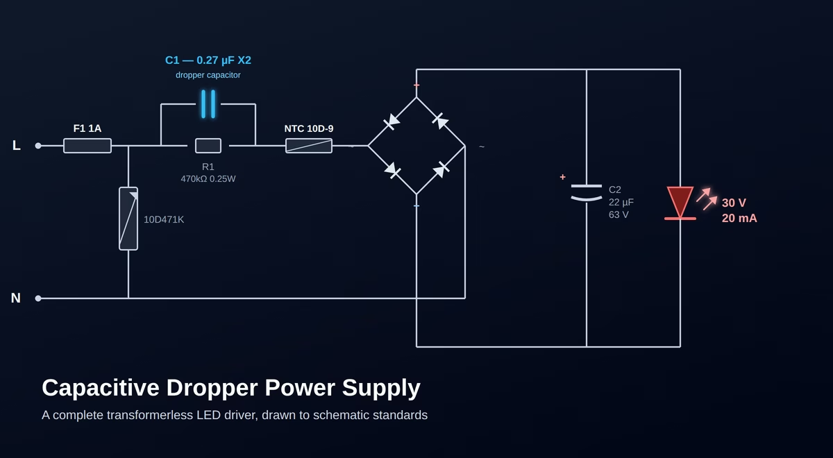
Sometimes in inexpensive LED bulbs from the supermarket, instead of a driver with an inductor, you can find a board strewn with just a few components, the main one being a large film capacitor. This is the classic transformerless power supply based on a capacitive dropper.
Many look at such circuits with disdain, calling them a relic of the past. But the laws of physics do not age. With a proper calculation, this circuit is capable of outliving the lamp itself and working for a very long time if high-quality components are used. I want to briefly explain how it works and how to build a truly reliable LED driver on a capacitive dropper with your own hands. You can even use point-to-point wiring (dead bug style).
To calculate the simplest circuit for connecting an LED to a power supply, use the LED resistor calculator↗. It is most commonly used for connecting indicator LEDs.
1. What is a capacitive dropper power supply?
A capacitive dropper power supply is the simplest circuit for converting high mains voltage (230V AC) into low DC voltage to power a relatively low-power load. Unlike modern switched-mode power supplies (SMPS), there are no high-frequency transformers or switching transistors here. Voltage reduction occurs entirely due to the reactive impedance of the dropping capacitor. It is the cheapest possible power supply, yet extremely reliable.
2. A dropping capacitor is a kind of "AC resistor" that doesn't get hot.
If we tried to drop the excess 200 Volts using an ordinary resistor to power a string of LEDs, this resistor would act like an oven, dissipating tens of Watts of heat. A crazy space heater. A dropping capacitor (usually an X2 class interference suppression film capacitor) uses its capacitance to limit the alternating current. The current is spent on an endless cycle of charging and discharging the capacitor plates at the mains frequency (50/60 Hz). The main magic is that no active thermal power is dissipated across the reactive impedance — the capacitor remains absolutely cold.
3. How it works in simple terms
Alternating current from the outlet passes through the dropping capacitor, which strictly doses (limits) the amount of amperes. Next, this limited alternating current hits the diode bridge, where it is rectified, turning into pulsating direct current. An electrolytic capacitor (filter) smooths out these pulsations so that the diodes do not flicker. Voila — a steady direct current is supplied to the LEDs. Of course, some level of ripple remains, but it is not too large and can be dealt with by adding, for example, an LC circuit or slightly increasing the capacitance of the output capacitor. Globally, it is better to use low current and high voltage than vice versa to obtain the desired power.
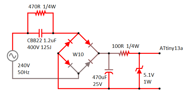
Sometimes simple capacitive dropper power supply circuits are used to power microcontrollers. Below is an example of the simplest circuit, where a Zener diode with a nominal value of 5.1V and a power of 1W is used as a voltage regulator. This circuit doesn't even include a protective resistor or NTC thermistor, which I will talk about below.
4. NTC Thermistor: Why do we need it?
If the circuit is so perfect, why is there a problem when flipping the switch? The problem lies in the inrush current. A completely discharged output capacitor (also known as a smoothing capacitor) has zero resistance in the first milliseconds of being turned on. If you close the circuit exactly at the peak of the mains sine wave (congratulations, you hit the jackpot!), a colossal current surge strikes the circuit, blowing out the diode bridge or, if not blowing it out, definitely sparking the switch contacts a bit. Sometimes it can even trip the circuit breaker.
To avoid this, a thermistor (NTC) is placed in the circuit, such as the popular 10D-9.
How it works: When the circuit is off, the thermistor is cold and has a resistance of about 10 Ohms. Upon power-up, it takes the current hit itself, protecting the diodes. Then, from the flowing operating current, it heats up, and its resistance drops to almost 0 Ohms. The protection worked, and no excess heat is generated during operation.
You can replace the NTC with a simple resistor, rated from 30 to 100 Ohms, but this will lower the efficiency of the power supply and increase heating. The resistor must have a fairly high power dissipation rating. The calculation of the resistor power is performed according to the formula: P = I² * R; where P is the resistor power, I is the current flowing in the circuit (the current limited by the capacitor) squared, and R is the resistor's resistance.
To help you quickly and easily understand the markings of modern resistors, we've created an online resistor color coding calculator↗ that works with 5% and 1% accuracy for resistors in the standard E24 and E96 series. The online calculator works in both directions: you can select colors and find the resistor's resistance, or enter the desired resistance and get the desired color coding.
5. Why is this circuit perfectly suited for LEDs and can act as an LED driver?
LEDs don't care about voltage; they need constant current. Current, as is known, is regulated through voltage and the total resistance of the circuit. Since the mains voltage (230V) is many times greater than the voltage drop across the LED string (for example, 30V), the dropping capacitor takes on the lion's share of the mains voltage. Under such conditions, the capacitor begins to behave like a current source. Small fluctuations in LED temperature or changes in their resistance have almost no effect on the total current in the circuit. They receive exactly the milliamperes that the capacitor let through. It sounds like a fairy tale, but alas, it's not that simple.
6. Advantages and Disadvantages (Is it reliable?)
Advantages:
- Absolute reliability (with proper calculation): The circuit has no complex microchips that can burn out from overheating. If the X2 capacitor is selected with a voltage margin (400V) and there is a thermistor at the input, the circuit works for decades. Assuming the smoothing electrolytic capacitor after the diode bridge doesn't dry out. But this problem is solvable. I'll write about this in the conclusion.
- No EMI (Electromagnetic Interference): The circuit does not generate high-frequency "garbage" into the airwaves and wires, which cheap switching drivers often sin with. Cheap, Chinese ones.
- Low cost: The cost of components is literally a few dollars, even if you choose exclusively branded, reliable components.
Disadvantages and Risks:
- DEADLY HAZARD (!!!): The circuit has no galvanic isolation from the mains. All elements, including the LEDs themselves, are under line voltage. Touching a working board with your bare hands is strictly unacceptable. It is best used with an RCD/GFCI (Residual Current Device).
- Power limitation: The circuit only makes sense for currents up to 100-150 mA. If you try to pull 700 mA, the dropping capacitor will be the size of a brick, and inrush currents will start tripping the breakers in the panel. Although you can get 700mA, in 99% of cases it makes no sense.
- Low Power Factor (Cos φ): For industrial scales, this type of load is probably not the best solution. Actually, in the industry, a much more cunning technology is used, effectively no more complicated but much cooler, but more on that in another article...
7. Where is it used today?
In the industry, such circuits are not put on powerful machine tools or workshop lighting — switching power supplies with galvanic isolation reign supreme there.
However, in everyday life, this topology is immortal. Capacitive droppers power: cheap LED bulbs (A-shape, candle, corn bulbs), smart relays for "smart home" systems (which need power without a neutral wire), night lights, indicators on dashboards, and some other electronics in well-insulated enclosures.
There is also an alternative technology Acrich from Seoul Semiconductor↗, with a patented circuit for connecting high-voltage LEDs.
8. Conclusions
A capacitive dropper power supply is a classic, like Vivaldi or Mozart. If you need to power a small LED lamp of 10-20 series-connected LEDs and the LED module will be securely hidden in an insulated plastic housing, this solution will save you money, and with good cooling, such an LED lamp can work without turning off for a good dozen years.
The main thing is to always do the mathematical calculation for your tasks and choose high-quality components, especially the smoothing capacitor. By the way, here you can use an assembly of film capacitors connected in parallel: they do not dry out like electrolytics and work for decades. Or you can choose expensive tantalum capacitors. To simplify the calculations, I created a widget that you can use to select the necessary element parameters in about 9 seconds. The diode bridge can be any, preferably rated for a current of 2 amps or more and a voltage of 1000 volts or more (a standard for almost all diode bridges).